Rigging system for supporting and pointing solar concentrator arrays

a solar concentrator and array technology, applied in the field of rigging, can solve the problems of insufficient solar flux for direct conversion at one solar flux to be cost effective, the effort to harness solar power on a large scale has so far failed to be economically competitive with most fossil-fuel energy sources, and the cost of solar concentrator systems is too high to compete unsubsidized with fossil fuels, etc., to achieve convenient and reliable cable tension adjustment and reduce bending forces

Inactive Publication Date: 2008-07-17
COOLEARTH SOLAR
View PDF38 Cites 117 Cited by
  • Summary
  • Abstract
  • Description
  • Claims
  • Application Information

AI Technical Summary

Benefits of technology

[0014]Particular embodiments may use ground mounted rigid posts to anchor the system and transmit compressive and other loads to the ground. Particular embodiments may further employ a system of guy cables and ground anchors to distribute loads to the ground and reduce bending forces in ground mounting posts. Particular embodiments of these ground anchors provide for adjustment of the relative guy cable position by means of a collet whose clamping force increases with guy-cable load. Particular embodiments of these ground anchors further provide for tightening of these collets via mechanical preloads provided by threaded elements. Particular embodiments of the ground anchor...

Problems solved by technology

However, attempts to harness solar power on large scales have so far failed to be economically competitive with most fossil-fuel energy sources.
Another reason for the lack of adoption of solar energy sources on a large scale is that the solar flux is not intense enough for direct conversion at one solar flux to be cost effective.
So far, however, solar concentrator systems cost too much to compete unsubsidized with fossil fuels, in part because of excessive material and instal...

Method used


Image

  • Rigging system for supporting and pointing solar concentrator arrays
  • Rigging system for supporting and pointing solar concentrator arrays
  • Rigging system for supporting and pointing solar concentrator arrays

Examples


embodiment 100

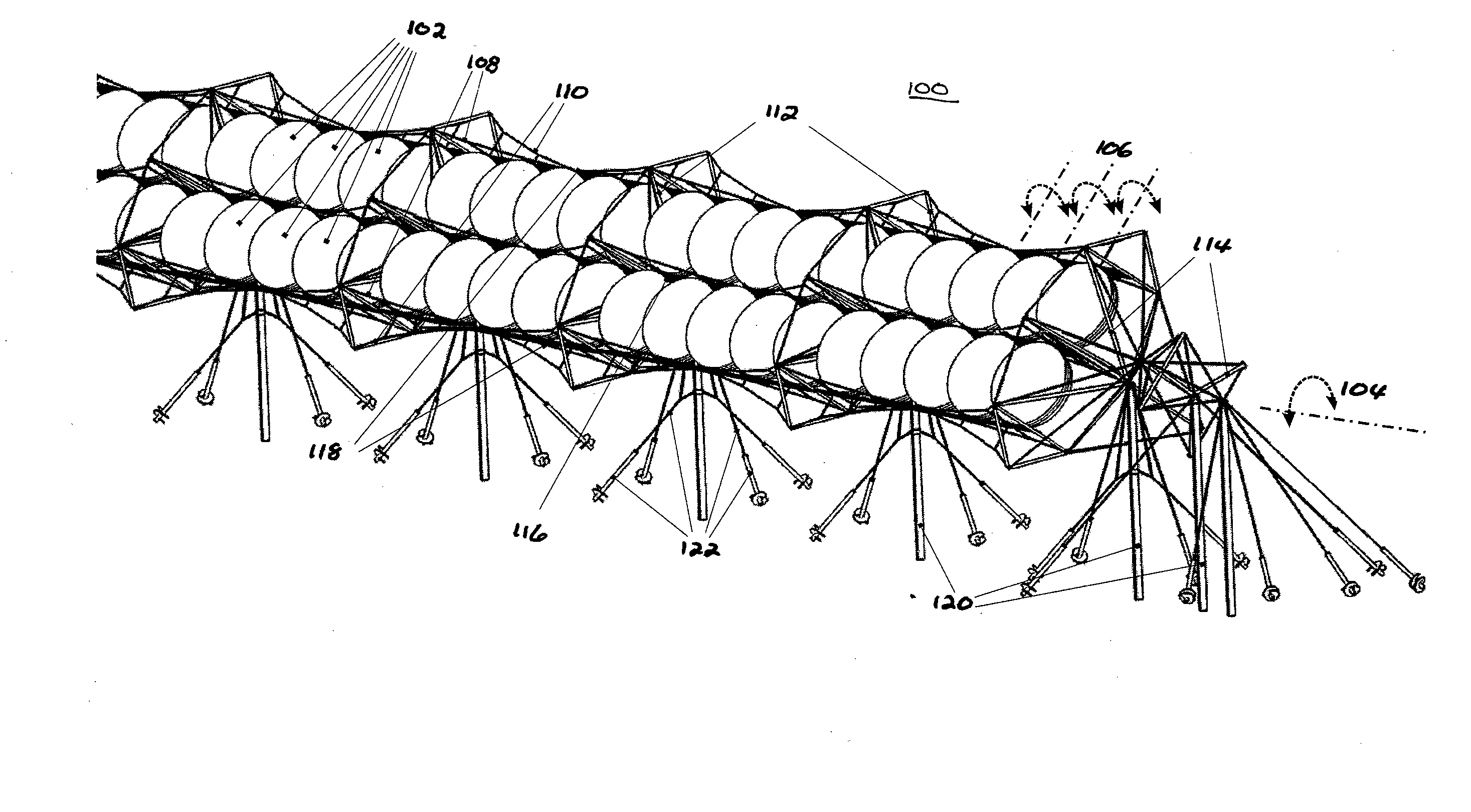
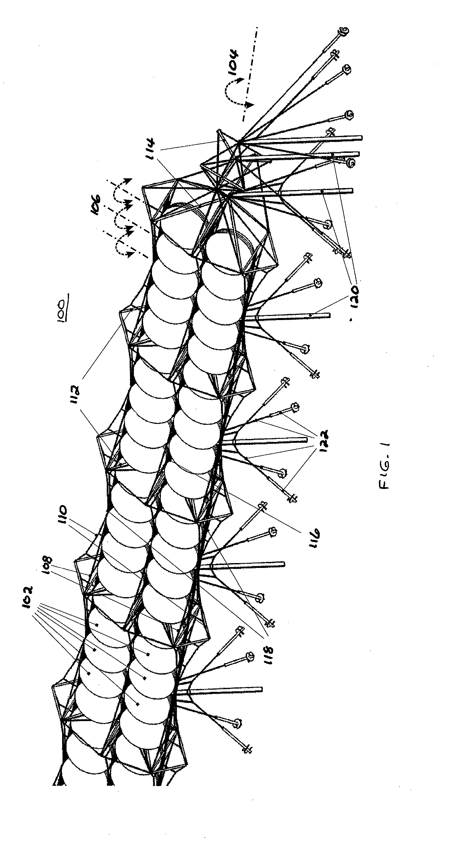
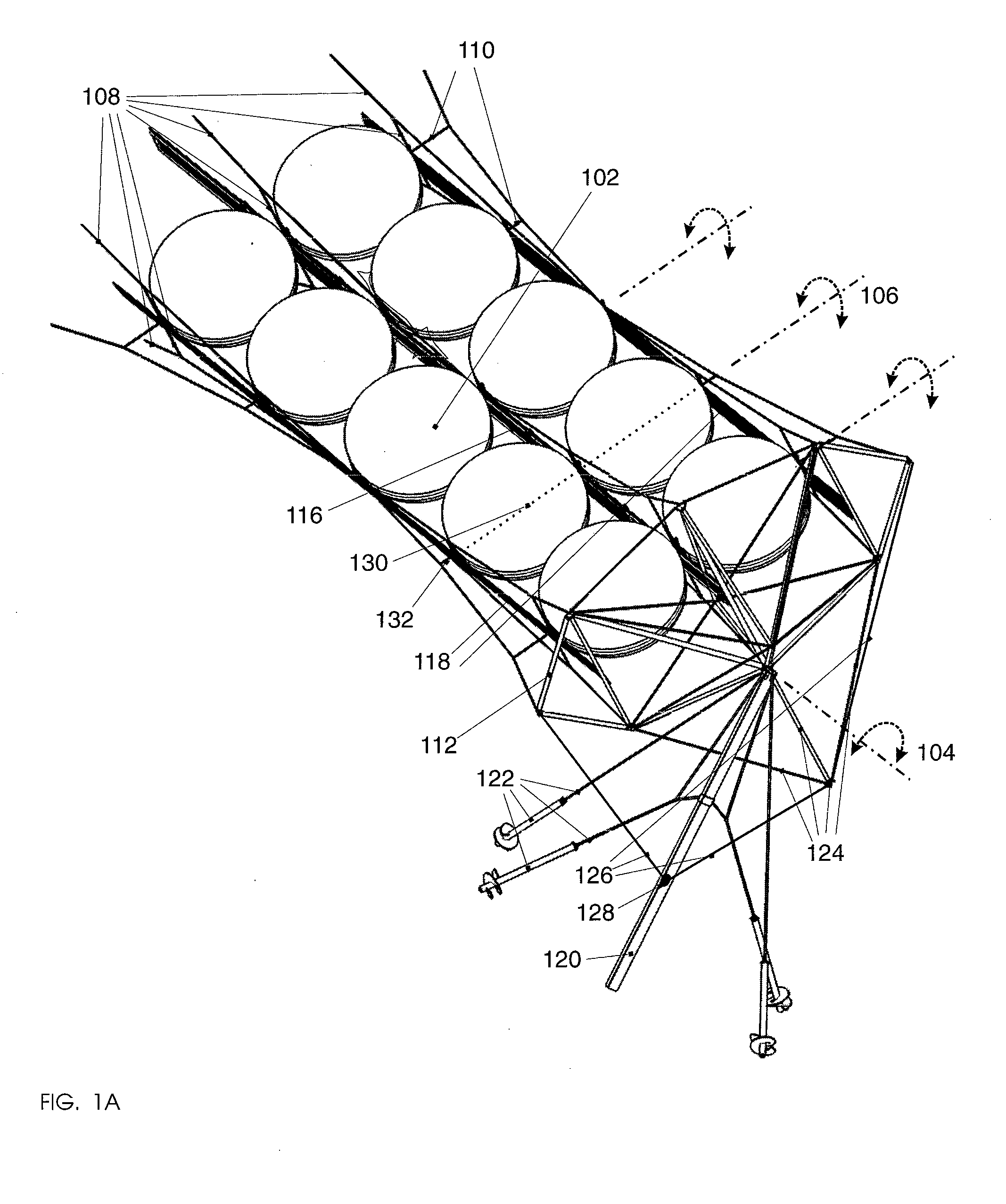
[0052]Embodiments in accordance with the present invention relate to the design of inexpensive and minimum-material mounting and pointing apparatus for linear arrays of solar energy collectors and converters. Particular embodiments in accordance with the present invention disclose the design of a rigging system comprising at least one tensile cable onto which a plurality of solar modules are fastened, thus providing a means of suspending solar modules over land, vegetation, bodies of water, and other geographic features without preparation of perturbation of the underlying terrain. One such embodiment 100 is shown in FIG. 1. FIG. 1A shows details for a typical interior segment of the array in FIG. 1 for clarity.

[0053]Elements 102 in FIGS. 1 and 1A are two-dimensional solar concentrators that require accurate pointing and tracking of the sun along two rotational axes. In this embodiment, the diameter of these concentrators is 2.5 m and the distance between vertical posts is 20 m. The...

embodiment 300

[0088]In this embodiment 300, a damper 320 is connected to the truss through an element 318. Damper 320, may be a hollow member partially filled with liquid or a solid, functions to limit vibration or flutter of the truss in response to external forces such as wind.

[0089]Another aspect in accordance with embodiments of the present invention is the mechanism to provide common axial motion of cables fastened to the modules to effect axial motion of the modules as shown in the embodiment of FIG. 5A. Such motion is useful for example to minimize shadowing effects between adjacent rows of solar modules disposed on different cable systems at different times of day and different days of the year. This common axial displacement can be fixed at install time, manually adjusted, or actuated.

[0090]A further element of embodiments in accordance with this invention is a mechanism that provides for the common translation of at least the cables fastened to the concentrator in a direction having a c...

embodiment 700

[0110]FIG. 7 shows an embodiment 700 of such an actuation method, taking the frame of reference of the truss. The compressive truss 702 is rotated about its pivot point 720 by drawing and feeding cables 708 and 710 using mechanism 712. Driving mechanism 712 can alternatively be mounted on the truss to be actuated and the cables 708 and 710 pull on points and over pivots that lie in another frame of reference, e.g., that of the ground or of another truss element. The cables 708 and 710, which can be portions of the same cable or two distinct cables, pull directly on the truss at points 716.

[0111]Over some angular range, 708 and 710 lay across a contact point 718 that is held in place by the truss members 704. This contact point prevents the lever arm between the cables 708 and 710 and the pivot from varying too greatly with the rotation of the truss. The contact point 718 and the two points 716 can be viewed as a triangular approximation of a circular arc. The use of additional pivot...


PUM

PropertyMeasurementUnit
Lengthaaaaaaaaaa
Forceaaaaaaaaaa
Electrical resistanceaaaaaaaaaa

Abstract

Embodiments in accordance with the present invention relate to the design of inexpensive mounting and pointing apparatuses for linear arrays of solar energy collectors and converters. Particular embodiments in accordance with the present invention disclose a rigging system comprising at least one, and preferably a plurality of, tensile cables onto which a plurality of solar modules are fastened. Such an arrangement provides a way of suspending solar modules over land, vegetation, bodies of water, and other geographic features without substantial perturbation of the underlying terrain. Certain embodiments comprise additional tensile cables fastened to the solar modules, such that differential axial motion of the cables produces a rotational motion component of the individual solar modules of the array. This rotational motion component effects an orientation control along one rotational axis.

Description

CROSS-REFERENCES TO RELATED APPLICATIONS[0001]The instant nonprovisional patent application claims priority to U.S. Provisional Patent Application No. 60 / 840,110, filed Aug. 25, 2006 and incorporated by reference in its entirety herein for all purposes. The instant nonprovisional patent application is also related to the following provisional patent applications, the disclosures of which are incorporated by reference in their entireties herein: U.S. Provisional Patent Application No. 60 / 839,841 filed Aug. 23, 2006; U.S. Provisional Patent Application No. 60 / 839,855 filed Aug. 23, 2006; and U.S. Provisional Patent Application No. 60 / 840,156 filed Aug. 25, 2006.BACKGROUND OF THE INVENTION[0002]Solar radiation is the most abundant energy source on earth. However, attempts to harness solar power on large scales have so far failed to be economically competitive with most fossil-fuel energy sources.[0003]One reason for the lack of adoption of solar energy sources on a large scale is that ...

Claims


Application Information

Patent Timeline
IPC IPC(8): F24J2/00B21D39/00E04H12/20E04C3/02E21D21/00
CPCF24J2/5241F24J2/54F24J2002/5458Y10T29/49826Y02E10/52H02S20/00H01L31/0547Y02E10/47H02S20/30H02S20/10F24S2030/133F24S25/50F24S30/40
Inventor CUMMINGS, ERIC BRYANTPACE, KIRSTEN KAYEBELANGER, JACQUES JEAN
Owner COOLEARTH SOLAR
Why Eureka
Try Eureka