Liquid crystal display and driving method thereof

a technology of liquid crystal display and driving method, which is applied in the direction of instruments, computing, electric digital data processing, etc., can solve the problems of degrading the display quality of motion pictures, and achieve the effect of improving display quality, preventing dc image sticking and flickering

Active Publication Date: 2008-07-17
LG DISPLAY CO LTD
View PDF10 Cites 70 Cited by
  • Summary
  • Abstract
  • Description
  • Claims
  • Application Information

AI Technical Summary

Benefits of technology

[0014]An object of the present invention is to provide a liquid crystal device and a driving method thereof for improving display quality by preventing DC image sticking and flicker.

Problems solved by technology

In a liquid crystal display device, the display quality of motion pictures is degraded not only because of the DC image sticking, but also because of a flicker phenomenon caused by a visual perception of difference in brightness.

Method used


Image

  • Liquid crystal display and driving method thereof
  • Liquid crystal display and driving method thereof
  • Liquid crystal display and driving method thereof

Examples


first embodiment

[0071]As shown in FIG. 5, an exemplary method for driving a liquid crystal display device according to the present invention inverts the polarity of a data voltage supplied to a liquid crystal cell Clc every frame period and then maintains the same polarity as the previous frame period at each Nth-multiple frame period.

[0072]‘N’ is preferably an integer of not less than 8 because it has been found experimentally that DC image sticking does not seem to appear either in interlace data or scroll data when N is an integer of not less than 8. However, other values of ‘N’ may be used without departing from the scope of the present invention.

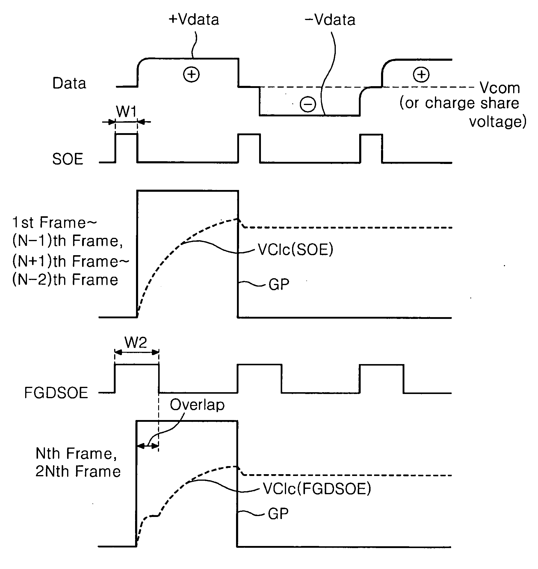
[0073]Furthermore, as shown in FIG. 6, the exemplary driving method according to the first embodiment of the present invention generates a first source output enable signal SOE having a first pulse width W1 during the first to (N−1)th frame periods, and a second source output enable signal FGDSOE having a second pulse width W2, which is wider than the ...

third embodiment

[0113]Specifically, the exemplary driving method of the liquid crystal display device according to the present invention increases the data charge amount of the liquid crystal cell by controlling the pulse width of the source output enable signal SOE supplied to the data drive circuit for the aging period. (S191 and S192) As described above, the amount of data voltage charged in the liquid crystal cell may be controlled by the width of the source output enable signal SOE. Accordingly, by generating a source output enable signal SOE to have a narrow pulse width, the amount of data voltage charged in the liquid crystal cell may be increased. Further, the present invention generates the polarity control signal, which is supplied to the data drive circuit for the aging period, as the first polarity control signal POL shown in FIG. 16, thereby inverting the polarity of the data voltage for each frame period. (S193)

[0114]Through experimentation, it has been found that if the liquid crysta...

fifth embodiment

[0125]The exemplary driving method of the liquid crystal display device according to the present invention may be implemented according to the liquid crystal display device shown in FIG. 18 with the addition of an aging stabilization circuit 234, as shown in FIG. 23, in combination with the POL / SOE logic circuit of the liquid crystal display device shown in FIG. 18. As shown in FIGS. 18 to 25, the POL / SOE logic circuit 162 determines the aging period by counting the supply period of the power supply voltage Vcc, generates either the first or second polarity control signals POL, FGDPOL during the aging period, and outputs the first source output enable signal SOE during the aging period. The POL / SOE logic circuit 162 outputs the second polarity control signal FGDPOL and the second source output enable signal FGDSOE in response to the first logic value of the selection signal SEL3 from the image analyzing circuit 161 after the aging period when data that is likely to generate DC image...


PUM


Abstract

A liquid crystal display device includes a liquid crystal display panel including a plurality of data lines to which a data voltage is supplied, a plurality of gate lines to which a gate pulse is supplied, and a plurality of liquid crystal cells, a data drive circuit to invert a polarity of the data voltage in response to a polarity control signal and to output the data voltage to the data lines in response to a source output enable signal, a gate drive circuit to supply the gate pulse to the gate lines, and a POL/SOE logic circuit to invert the polarity control signal for every frame period except at Nth-multiple frame period (where N is a positive integer), wherein the POL/SOE logic circuit controls the polarity control signal at every Nth-multiple frame period such that the polarity of the data voltage is the same as the previous frame period and controls a pulse width of the source output enable signal at every Nth-multiple frame period to be longer than for the other frame periods.

Description

[0001]This application claims the benefit of the Korean Patent Application Nos. P2007-0004255 filed Jan. 15, 2007, P2007-0019587 filed Feb. 27, 2007, P2007-0028228 filed Mar. 22, 2007, P2007-0035126 filed Apr. 10, 2007, and P2007-0037936 filed Apr. 18, 2007, which are hereby incorporated by reference.BACKGROUND OF THE INVENTION[0002]1. Field of the Invention[0003]The present invention relates to a liquid crystal display device, and more particularly to a liquid crystal display device that is adaptive for increasing display quality by preventing flickers and DC image sticking, and a driving method thereof.[0004]2. Discussion of the Related Art[0005]A liquid crystal display device controls the light transmittance of liquid crystal cells in accordance with video signals, thereby displaying a picture. An active matrix type liquid crystal display device actively controls the displayed images by switching data voltages supplied to a thin film transistor TFT formed at each liquid crystal c...

Claims


Application Information

Patent Timeline
Patent Type & Authority Applications(United States)
IPC IPC(8): G09G3/36
CPCG09G3/3614G09G2330/023G09G3/3688G09G2310/0205G09G2310/0224G09G2310/0248G09G2310/0251G09G2310/027G09G2310/08G09G2320/0204G09G2320/0247G09G2320/048G09G2320/0613G09G2320/103G09G3/3648
Inventor SONG, HONG SUNGMIN, WOONG KICHOI, BYUNG JINKIM, DONG ILJANG, SU HYUK
Owner LG DISPLAY CO LTD
Why Eureka
Try Eureka