
Control device, control method, and storage apparatus

Inactive Publication Date: 2008-07-17
TOSHIBA STORAGE DEVICE CORP
View PDF11 Cites 13 Cited by
  • Summary
  • Abstract
  • Description
  • Claims
  • Application Information

AI Technical Summary

Benefits of technology

[0008]According to the present invention to provide a control device, a control method, and a storage apparatus capable of precisely measuring the clearance upon recording involving heater electric power distribution and controlling the clearance at high precision.
[0040]According to the present invention, when the variance is less than a predetermined threshold value, a recording operation is performed while sequentially increasing write heat electric power, immediately after that, it is switched to a reproduction operation, and a process of performing amplitude measurement is repeated so as to detect contact between the head and the medium. In the contact between the head and the medium, a pumping phenomenon in which the head jumps due to collision with small protrusions when the contact with the medium is started occurs. Therefore, it is switched to the reproduction operation in the state in which the pumping phenomenon is generated. Detection is performed when the variation of the amplitude measurement values in that process or the variance of the measured values exceeds a threshold value, and the fact that the head is in contact with the medium is precisely determined. When contact between the medium of head and the medium can be precisely determined, the write clearance can be precisely calculated from the varied amount of the heater electric power up to the contact determination. Since the clearance upon recording, in which the head is subjected to write heat to write data, can be precisely measured in this manner, the clearance can be controlled to a minimum clearance for each head and recording position (zone) of the medium without impairing the flying margin upon recording / reproduction, thereby improving error rate. The above and other objects, features, and advantages of the present invention will become more apparent from the following detailed description with reference to the drawings.

Problems solved by technology

In a conventional head, since the clearance is maintained merely by the pressure of air, variation in the clearance generated among heads, for example, variation in the clearance due to the environmental temperature, mounting variation generated upon mounting of magnetic heads, and manufacturing variation generated among heads cannot be corrected.
However, since variations of the clearances are present among heads within common differences of mechanisms, there is a problem that the clearance cannot be set smaller than the range of common differences when medium contact is taken into consideration.
Moreover, since a medium rotates at a high speed in a magnetic disk apparatus, collision with minute protrusions of the magnetic disk surface readily occurs when the clearance of the head is reduced; and, when the medium and the magnetic head are brought into contact with each other, there is a problem that the life of the apparatus cannot be satisfied due to wear of the head and contamination (dust) or the like that is generated when the head is brought into contact with the medium.
However, the above described methods, in which a heater is provided in a head to control the clearance between it and a magnetic disk recording surface, have a problem that the clearance upon recording cannot be measured even when the clearance upon reproduction can be measured although the clearance has to be measured both upon the reproduction performed by electric power distribution to the heater and the recording performed by electric power distribution to the heater, and the heater electric power that controls the clearance to an optimal target clearance upon reproduction and recording cannot be precisely determined.
Meanwhile, upon recording, in addition to expansion and protrusion of the head flying surface that is caused by electric power distribution to and heating of the heater, there is heat generating expansion that is caused when a recording current flows through a recording coil of the head; therefore, in the method in which the clearance is measured by performing reproduction and error detection after data is recorded, the clearance upon recording wherein the clearance is further reduced cannot be clarified, and precise clearance control by heater electric power distribution is difficult.
In the clearance measurement that is based on error detection of a head read signal, there is a problem that the error detection accuracy obtained through recording / reproduction is dependent on the recording performance of a recording element and reproduction output power of a reading element, error detection sensitivity is different among heads, and precise clearance measurement is difficult to perform.

Method used


Image

  • Control device, control method, and storage apparatus
  • Control device, control method, and storage apparatus
  • Control device, control method, and storage apparatus

Examples


Embodiment Construction

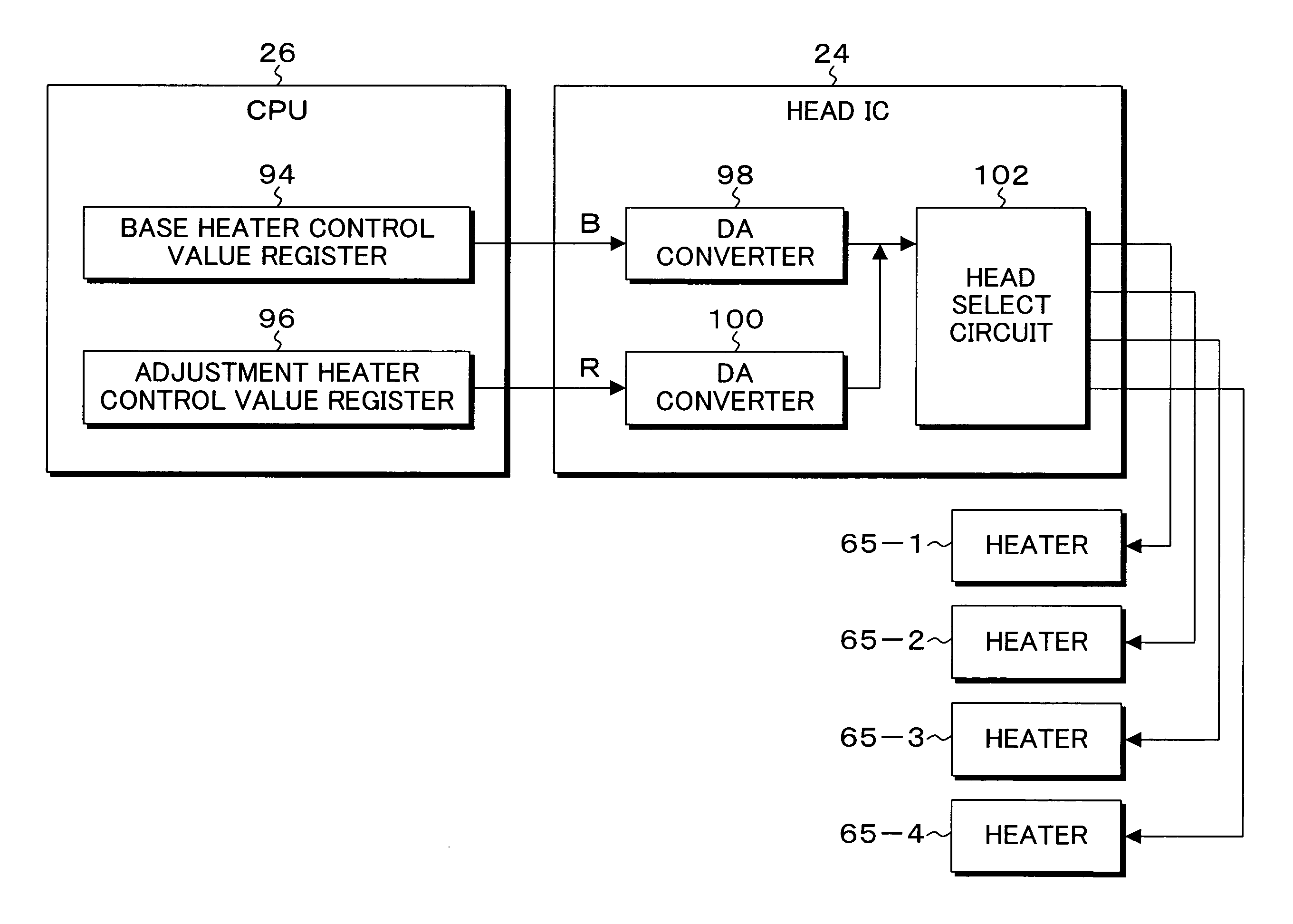
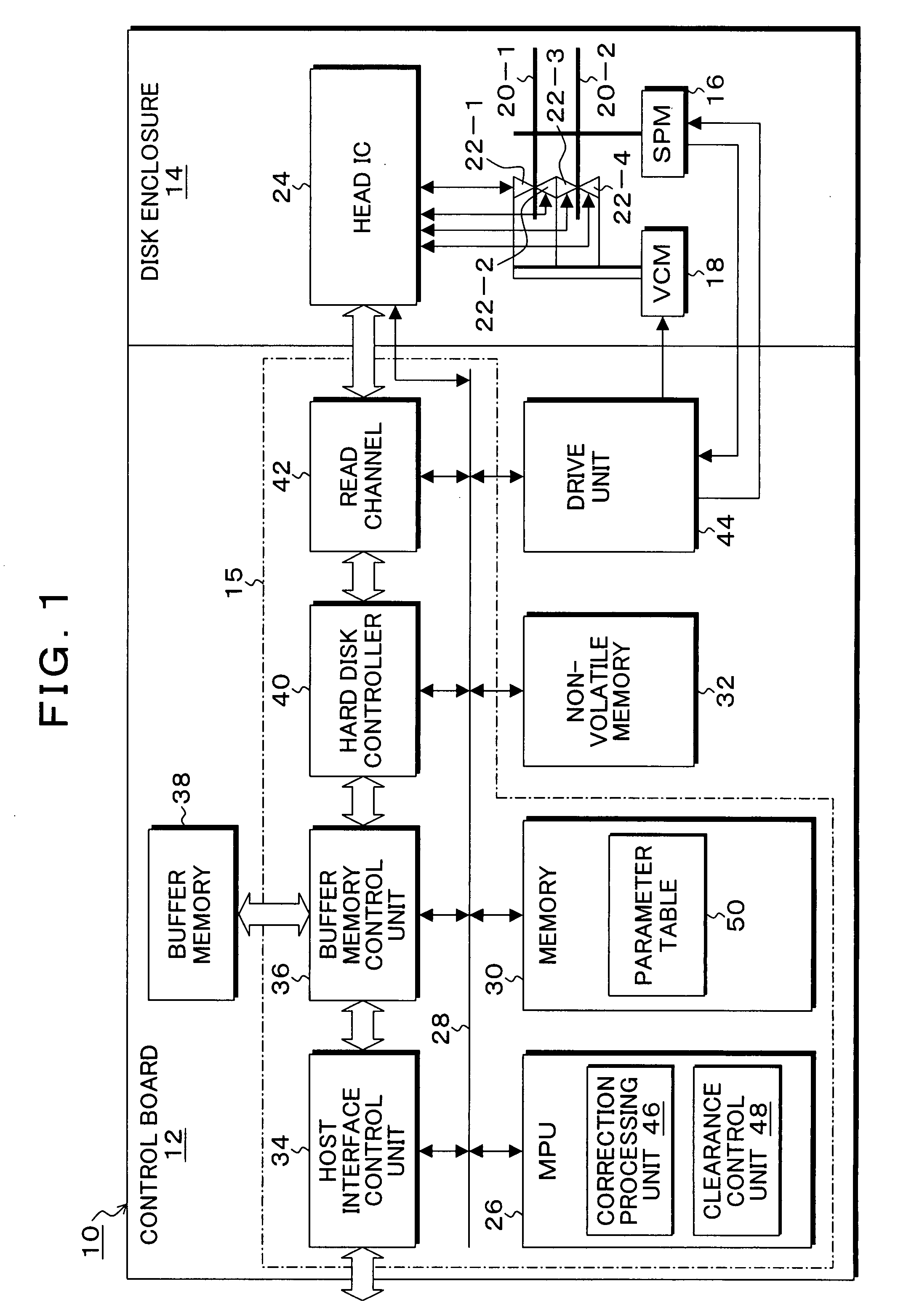
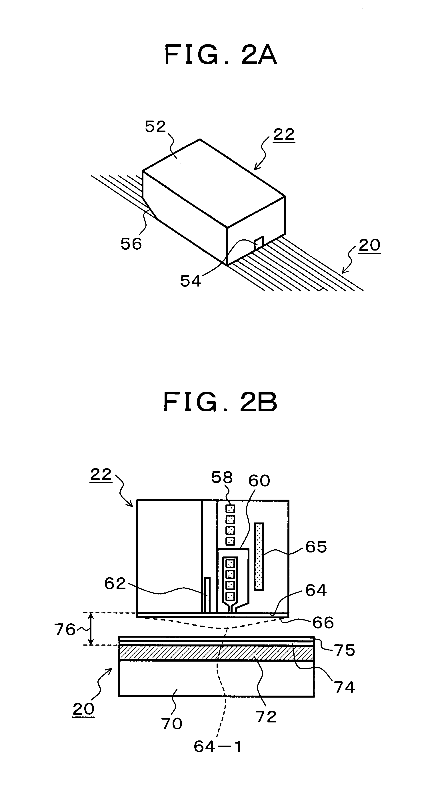
[0057]FIG. 1 is a block diagram showing an embodiment of a magnetic disk apparatus according to the present invention. In FIG. 1, the magnetic disk apparatus 10 which is known as a hard disk drive (HDD) is composed of a disk enclosure 14 and a control board 12. A spindle motor (SPM) 16 is provided in the disk enclosure 14; and magnetic disks (storage media) 20-1 and 20-2 are attached to a rotating shaft of the spindle motor 16 and rotated at, for example, 4200 rpm for a certain period of time. In addition, a voice coil motor (VCM) 18 is provided in the disk enclosure 14, wherein the voice coil motor 18 has distal ends of arms of head actuators on which heads 22-1 to 22-4 are loaded and performs positioning of the heads with respect to recording surfaces of the magnetic disks 20-1 and 20-2. In addition, recording elements and reading elements are loaded on the heads 22-1 to 22-4 in an integrated manner. The heads 22-1 to 22-4 are connected to a head IC 24 by signal lines, and the hea...


PUM


Abstract

Upon correction, an amplitude measurement unit repeats a process of attaining a write heat state by a write clearance control unit and writing user data to a data region of a measurement track in the state in which a head is positioned to an arbitrary measurement track and then switching the state to a read heat state by a read clearance control unit so as to detect an amplitude of a read signal from a preamble unit in a servo region. A variance calculation unit calculates a variance from the plurality of amplitude measurement values measured by the amplitude measurement unit; and a contact determination unit repeats the measurement process by the amplitude measurement unit while sequentially increasing the base heater control value when the variance is less than a predetermined threshold value and determines contact between the head and the medium when the variance exceeds the threshold value. The write clearance calculation unit calculates the clearance upon write heat of the head from the increased amount of the base heater control value upon contact determination.

Description

[0001]This application is a priority based on prior application No. JP 2007-005507, filed Jan. 15, 2007, in Japan.BACKGROUND OF THE INVENTION[0002]1. Field of the Invention[0003]The present invention relates to a control device, a control method, and a storage apparatus for causing a head to fly above a rotating storage medium so as to read / write data and particularly relates to a control device, a control method, and a storage apparatus for controlling the clearance between a head and a storage medium surface to a predetermined target clearance by varying a protrusion value by thermal expansion that occurs along with power distribution to and heating of a heater provided in a head.[0004]2. Description of the Related Arts[0005]Conventionally, the clearance between a recording surface of a magnetic disk and a head has to be reduced in order to realize high recording density of a magnetic disk apparatus, and the clearance generated by flying of the head is designed to be constant by u...

Claims


Application Information

Patent Timeline
IPC IPC(8): G11B21/21
CPCG11B5/6029G11B5/6005G11B5/455G11B5/5534G11B5/607G11B5/6076
Inventor SHIMOZATO, TORU
Owner TOSHIBA STORAGE DEVICE CORP
Learn More