
Switched capacitor circuit and pipeline a/d converter

Active Publication Date: 2010-02-25
ASAHI KASEI ELECTRONICS CO LTD
View PDF3 Cites 3 Cited by
  • Summary
  • Abstract
  • Description
  • Claims
  • Application Information

AI Technical Summary

Benefits of technology

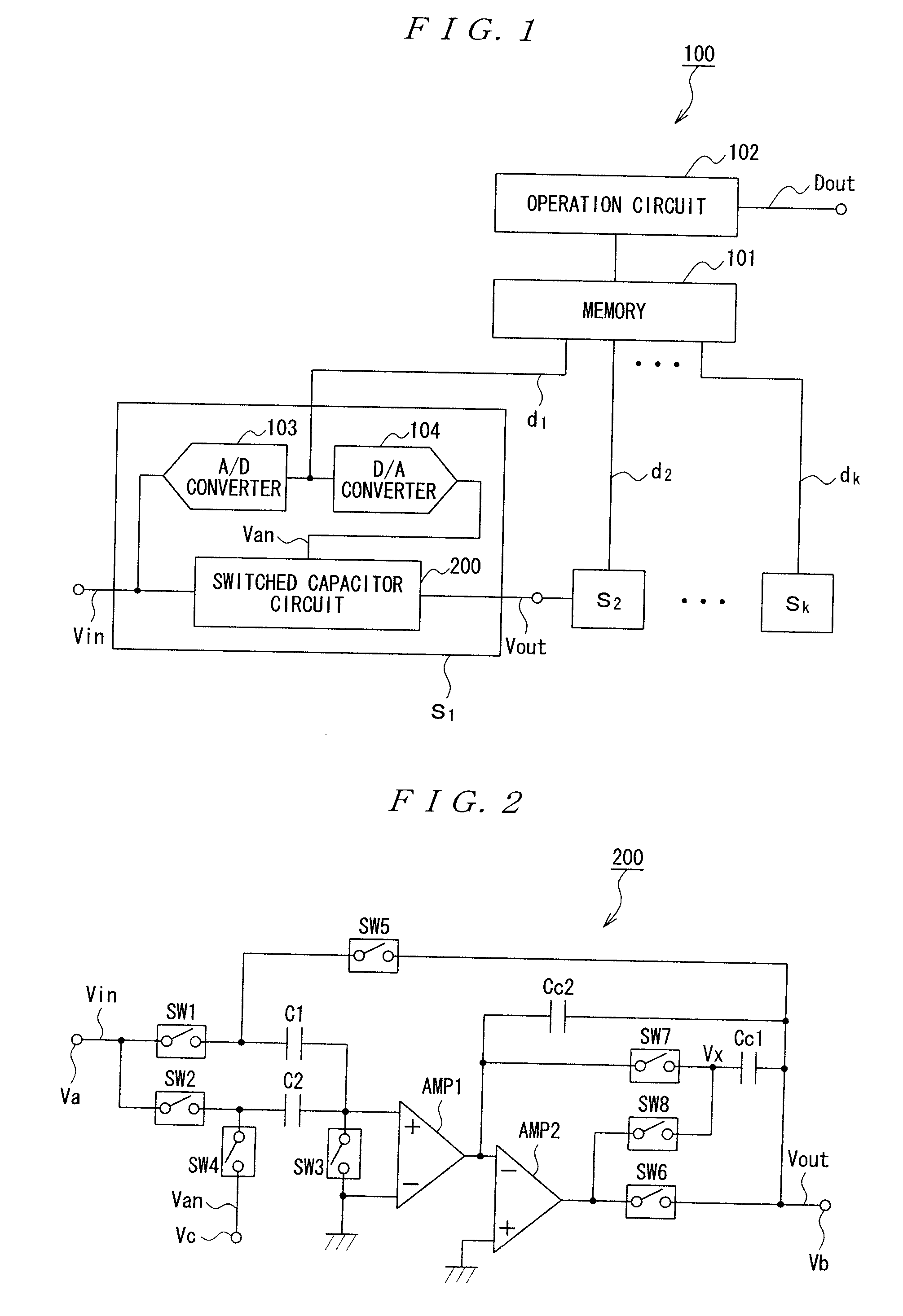
[0029]In the above described configuration, the level shift capacitor is not only used to sample and level-shift the signal outputted from the operational amplifier, but also is used, in the estimate phase, to sample the amplified analog input signal and to compensate the phase of the operational amplifier. When the phase is compensated in the estimate phase, the level shift capacitor is connected in the loop between the output terminal and the inverting input terminal of the operational amplifier. Hence, the load imposed on the level shift capacitor in the operational amplifier is reduced according to the gain A of the operational amplifier. This reduces the load imposed on the operational amplifier by the level shift capacitor and the phase compensation capacitor, as compared with a case where the phase is compensated by only the phase compensation capacitor. As a result, the electric power in the switched capacitor circuit can be significantly reduced.
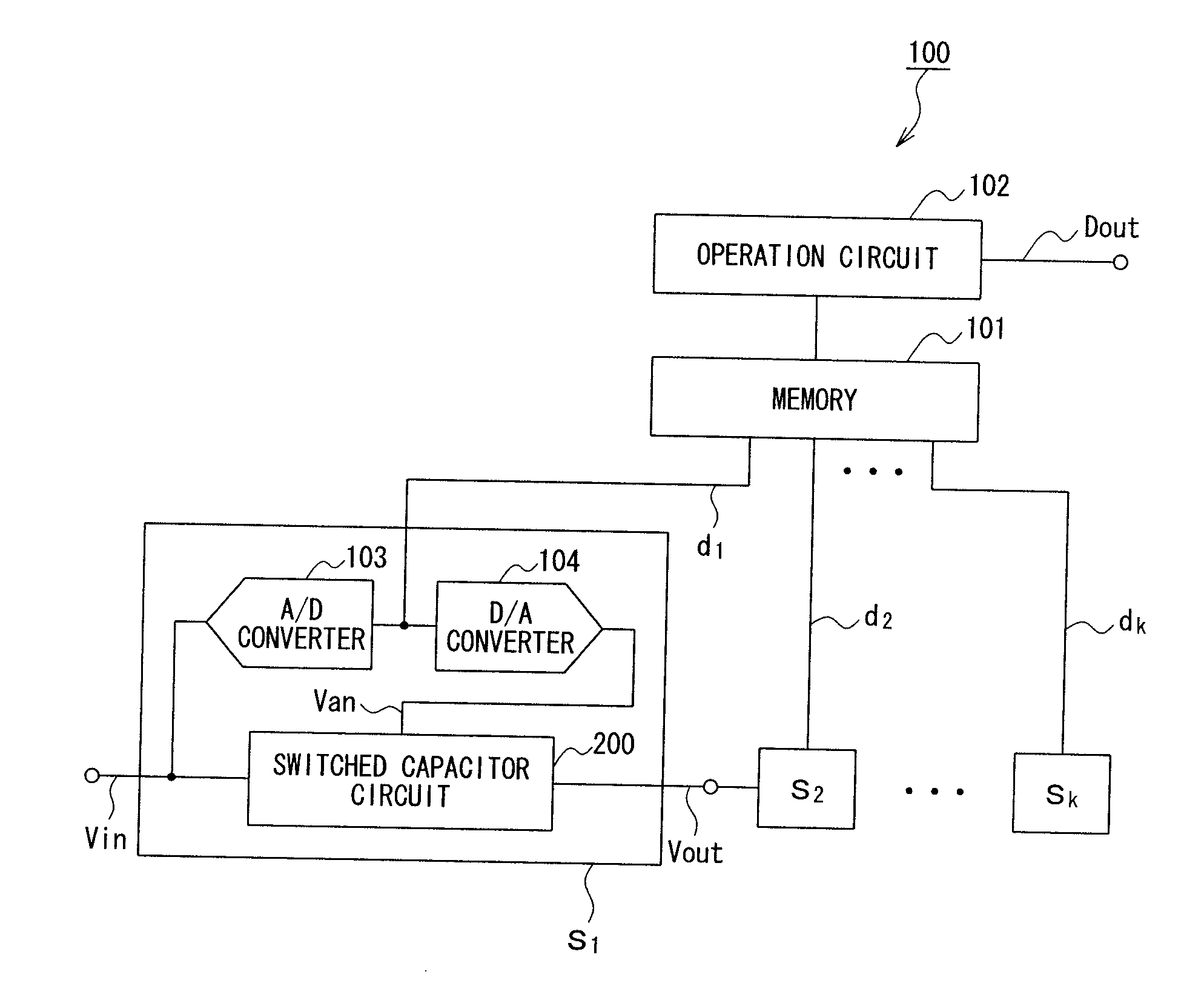
[0044]Moreover, each of the stages included in the pipeline A / D converter is configured with the switched capacitor circuit as described above, and hence the power consumption in each of the stages is reduced. For this reason, even in a case where the pipeline A / D converter is configured with the plurality of stages, it is possible to significantly reduce the power consumption in the entire pipeline A / D converter. Likewise, it is possible to reduce the size of the entire pipeline A / D converter, and to reduce manufacturing cost.

Problems solved by technology

For this reason, sufficient output accuracy may not be obtainable in the event that the gain A of the operational amplifier AMP1 is not sufficiently large.
This causes the output amplitude to be limited.

Method used


Image

  • Switched capacitor circuit and pipeline a/d converter
  • Switched capacitor circuit and pipeline a/d converter
  • Switched capacitor circuit and pipeline a/d converter

Examples


first embodiment

[0075]Subsequently, with reference to FIG. 4, there will be described the output characteristic of the analog output signal of the switched capacitor circuit according to the present invention. FIG. 4 is a graph exhibiting the output characteristics of the analog output signals of the switched capacitor circuits.

[0076]In FIG. 4, the horizontal axis represents the time t and the vertical axis represents the analog output signal Vout of the switched capacitor circuit. The analog output signal Vout1 represents the output characteristic of the analog output signal Vout in the switched capacitor circuit 700 shown in FIG. 9. The analog output signal Vout2 represents the output characteristic of the analog output signal Vout in the switched capacitor circuit 200 illustrated in FIG. 2. The analog output signal Vout3 represents the output characteristic of the analog output signal Vout when the output band of the feedback system in the switched capacitor circuit 700 shown in FIG. 9 is lowere...

second embodiment

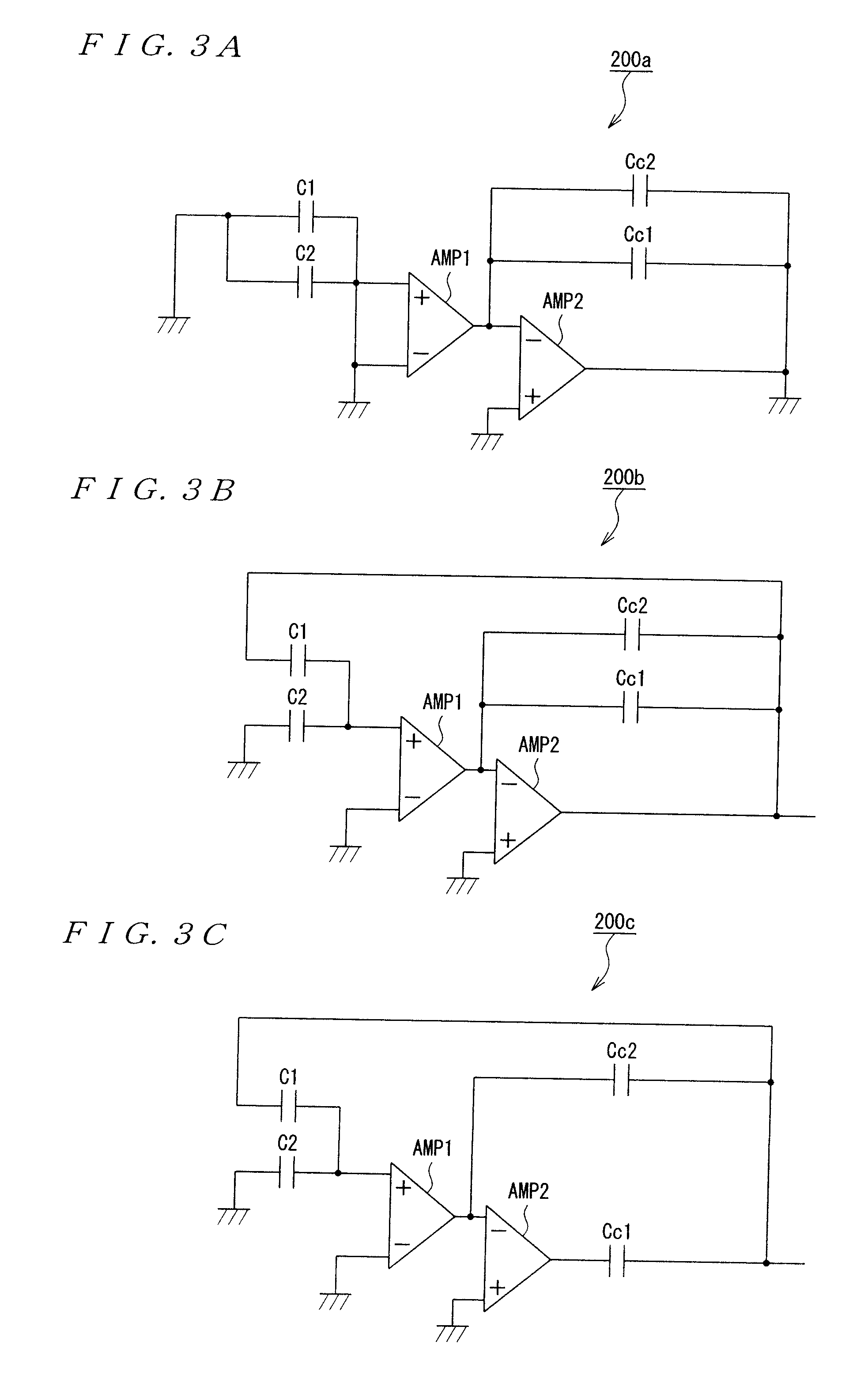
[0083]In the switched capacitor circuit 300 according to the present invention, the capacitor Cc2 is not connected in parallel to both the operational amplifier AMP2 and the CLS circuit, but is connected between the output terminal and the inverting input terminal of the operational amplifier AMP2, so as to compensate the phase of the operational amplifier AMP2. However, also in the switched capacitor circuit 300, the capacitors Cc1 and Cc2 perform compensate the phase of the operational amplifier AMP2 similarly to the switched capacitor circuit 200 illustrated in FIG. 2. For this reason, also in the switched capacitor circuit 300, while maintaining the advantages of the CLS technique, it is possible to suppress electric power to the same extent as in the conventional switched capacitor circuit 600 that does not utilize the CLS technique.

[0084]Subsequently, with reference to FIG. 6, there will be described a configuration of a switched capacitor circuit according to a modification o...


PUM


Abstract

There is provided a switched capacitor circuit and a pipeline A / D converter which are capable of suppressing electric power from being increased by utilizing a level-shift capacitor, even in a case where the switched capacitor circuit and the pipeline A / D converter are configured by utilizing a CLS technique. In the estimate phase, the capacitor Cc1 (level shift capacitor) is connected between the output terminal of the operational amplifier AMP2 and the inverting input terminal of the operational amplifier AMP2, so as to sample the output from the operational amplifier AMP2, and also to compensate the phase of the operational amplifier AMP2. Additionally, in the level shift phase, the capacitor Cc1 is connected between the output terminal of the operational amplifier 4 and the output terminal Vb, so as to be used to level-shift the output of the operational amplifier AMP2. Thereby, the load (the capacitance of the capacitors Cc1 and Cc2) on the operational amplifier AMP2 is reduced, thereby reducing the electric power of the switched capacitor circuit 200.

Description

BACKGROUND OF THE INVENTION[0001]1. Field of the Invention[0002]The present invention relates to switched capacitor circuits and pipeline A / D converters, and more particularly, to a switched capacitor circuit and a pipeline A / D converter which are configured by utilizing CLS (Correlated Level Shift) technique and which are operated with low power consumption.[0003]2. Description of the Related Art[0004]In various image sensors, image processing circuits, and the like, there are known pipeline A / D converters in which a plurality of stages are cascade-connected in multiple stages to convert an analog signal into a digital signal, in order to process several types of signals for one clock. Each of the stages is configured with a switched capacitor circuit, an A / D converter, and the like, so as to output a digital signal of predetermined bits corresponding to an analog input signal. The pipeline A / D converter synthesizes the digital signals outputted from the respective stages, so as to...

Claims


Application Information

Patent Timeline
IPC IPC(8): H03M1/02G11C27/02
CPCG11C27/026H03F3/005H03F3/45475H03M1/442H03F2203/45514H03M1/164H03F2203/45138
Inventor SANO, MITSUHIRO
Owner ASAHI KASEI ELECTRONICS CO LTD
Learn More