Head gimbal assembly with improved interconnection between head slider and suspension, fabricating method thereof, and magnetic disk drive with the same

Active Publication Date: 2008-07-17
SAE MAGNETICS (HK) LTD
View PDF9 Cites 27 Cited by
  • Summary
  • Abstract
  • Description
  • Claims
  • Application Information

AI Technical Summary

Benefits of technology

[0010]Accordingly, an object of the present invention is to provide a head gimbal assembly (HGA) with an improved interconnection between a head slider and a suspension of the HGA capable of controlling the attitude such as pit

Problems solved by technology

However, the method for interconnection the head slider 2 and the flexure 3 of the suspension described above is complicated.
The electrical and mechanical connection between the head slider 2 and the flexure 3 are two separate assembly processes, which are time-consuming and laborious.
Thus, a smaller size head slider can no longer provide enough space for bonding connection at the slider's trailing sur

Method used


Image

  • Head gimbal assembly with improved interconnection between head slider and suspension, fabricating method thereof, and magnetic disk drive with the same
  • Head gimbal assembly with improved interconnection between head slider and suspension, fabricating method thereof, and magnetic disk drive with the same
  • Head gimbal assembly with improved interconnection between head slider and suspension, fabricating method thereof, and magnetic disk drive with the same

Examples


first embodiment

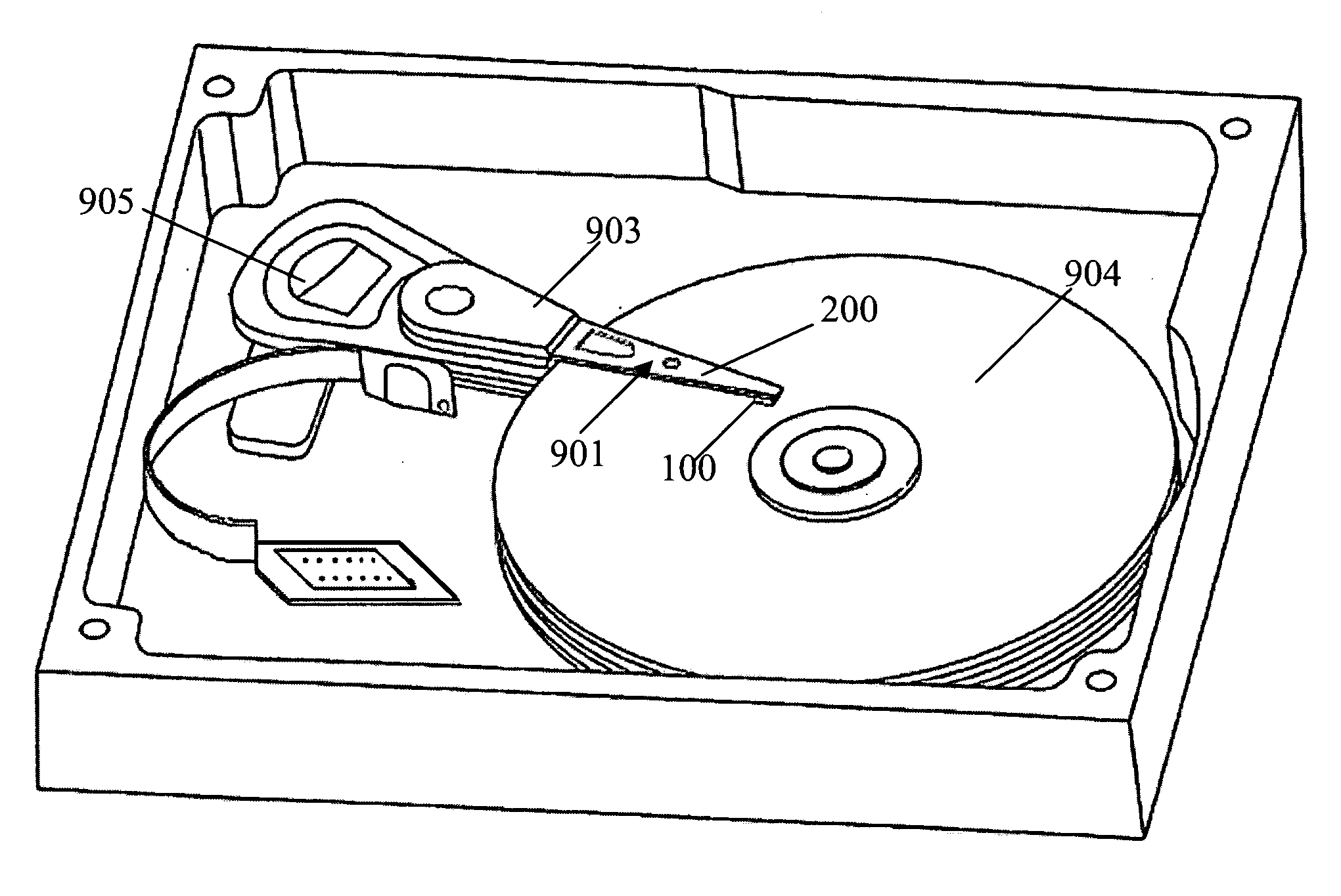
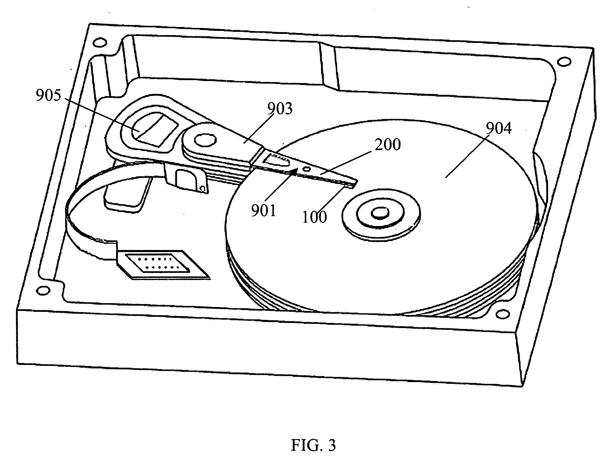
[0064]FIG. 5 is a perspective view of the head slider 100 of a first embodiment according to the present invention. The head slider 100 has an air bearing surface 111, a bonding surface 112 opposite to the air bearing surface 111, and a plurality of slider electrical bonding pads 131, 132, 133, and 135 as well as a ground trace 134 all arranged on the bonding surface 112. The head slider 100 also brings out a plurality of secondary bonding pads 114 located on a trailing surface 113 of the head slider 100, and the secondary bonding pads 114 electrically connects to the respective slider electrical bonding pads 131, 132, 133, and 135 for conducting the controlling signal from the read / write electronic circuitry. More particularly, the slider electrical bonding pads comprises one heater pad 132, one ground bonding pad 135 connecting the ground trace 134, a pair of reader bonding pads 131 for linking reading signals, and another pair of writer bonding pads 133 for linking writing signal...

second embodiment

[0074]Alternatively, the head slider 100 can be designed to possess some optimized structure according to the invention. FIG 11a shows a head slider 100a. As is shown, the head slider 100a comprises a slider body 110, a first insulation layer 120, a metal lead layer 130, a second insulation layer 140, and a semi-insulation layer 150, all of which are assembled together.

[0075]Referring to FIG. 11a in conjunction with FIG. 11b, the slider body 110 has an air bearing surface 111′, a bonding surface 112′ opposite to the air bearing surface 111′, a slider base 115, an overcoat 116, and an undercoat 117 between the slider base 115 and the overcoat 116. The secondary bonding pads 114 are formed on the undercoat 117. The slider body 110 is also provided with a read / write element 118 on the undercoat 117 and electrically connecting to each secondary bonding pad 114. Each secondary bonding pad 114 has one branch reaching to a trailing surface 113′ of the overcoat 116 for probing test in wafer...

third embodiment

[0080]FIG. 12a shows a head slider 100b of the present invention. The head slider 100b in the present embodiment is similar to the head slider 100a mentioned above except that the semi-insulation layer 150 of head slider 100b employs another way to ground the slider body 110. Concretely, the metal lead layer 130 provides an electro static discharge (ESD) bonding pad 136, and the semi-insulation layer 150 and the slider body 110 are respectively and electrically connected to the ESD bonding pad 136 through the first gap 121 defined in the first insulation layer 120 and the second gap 141 defined in the second insulation layer 140, thus realizing preventing ESD.


PUM


Abstract

A head gimbal assembly (HGA) has an improved interconnection between a head slider and a suspension of the HGA. The interconnection is achieved by using a reverse surface of an air bearing surface of the head slider as bonding surface to provide more space for arranging more slider electrical bonding pads thereon. The head slider is mechanically and electrically connected to the suspension at the bonding surface to have good performance on shocking conditions. The suspension further has an attitude control layer located between the head slider and the suspension. The attitude control layer serves as a datum plate for the head slider lying thereon and supporting the head slider so as to ensure the head slider a good attitude and reduce variation of slider flying height. The present invention also discloses a magnetic disk drive with the improved HGA and a fabricating method for the HGA.

Description

FIELD OF THE INVENTION[0001]The present invention relates in general to an information recording disk drive device. More particularly, this invention relates to a head gimbal assembly with an improved interconnection between a head slider and a suspension of the assembly, and a method for fabricating the head gimbal assembly, and a magnetic disk drive with the improved head gimbal assembly.BACKGROUND OF THE INVENTION[0002]Disk drives are information storage devices that use magnetic media to store data and a movable read / write head positioned over the magnetic media to selectively read data from and write data to the magnetic media.[0003]Typically, referring to FIG. 1, a disk drive contains a number of magnetic disks 6 attached to a common spindle motor for rotation. The surface of the magnetic disk 6 suspends an associated head arm assembly that includes a head gimbal assembly (HGA) 1. The head gimbal assembly 1 is generally attached to and mounted on a drive arm 4. A voice-coil mo...

Claims


Application Information

Patent Timeline
IPC IPC(8): G11B5/016G11B15/64
CPCG11B5/4853G11B5/486H05K2203/041H05K3/3436H05K2201/10424G11B5/6064Y02P70/50
Inventor FENG, XIANWENPEI, YIHUAZHANG, JUGANGZHANG, SHUMINGNAKADA, TAKESHIHAO, SHANLIN
Owner SAE MAGNETICS (HK) LTD
Why Eureka
Try Eureka