Method for forming carbon protective film and method for producing magnetic recording medium, magnetic recording medium and magnetic recording/reproducing apparatus
a technology of carbon protective film and magnetic recording medium, which is applied in the direction of magnetic layer protection, record information storage, instruments, etc., can solve the problems of fatal tribology between the magnetic head and the magnetic recording medium, insufficient durability of the material, and the inability to slide the head on the recording medium, etc., to achieve the effect of suppressing the accumulation of carbon protective film, effective suppressing the generation of particles, and excellent flatness
- Summary
- Abstract
- Description
- Claims
- Application Information
AI Technical Summary
Benefits of technology
Problems solved by technology
Method used
Image
Examples
example 1
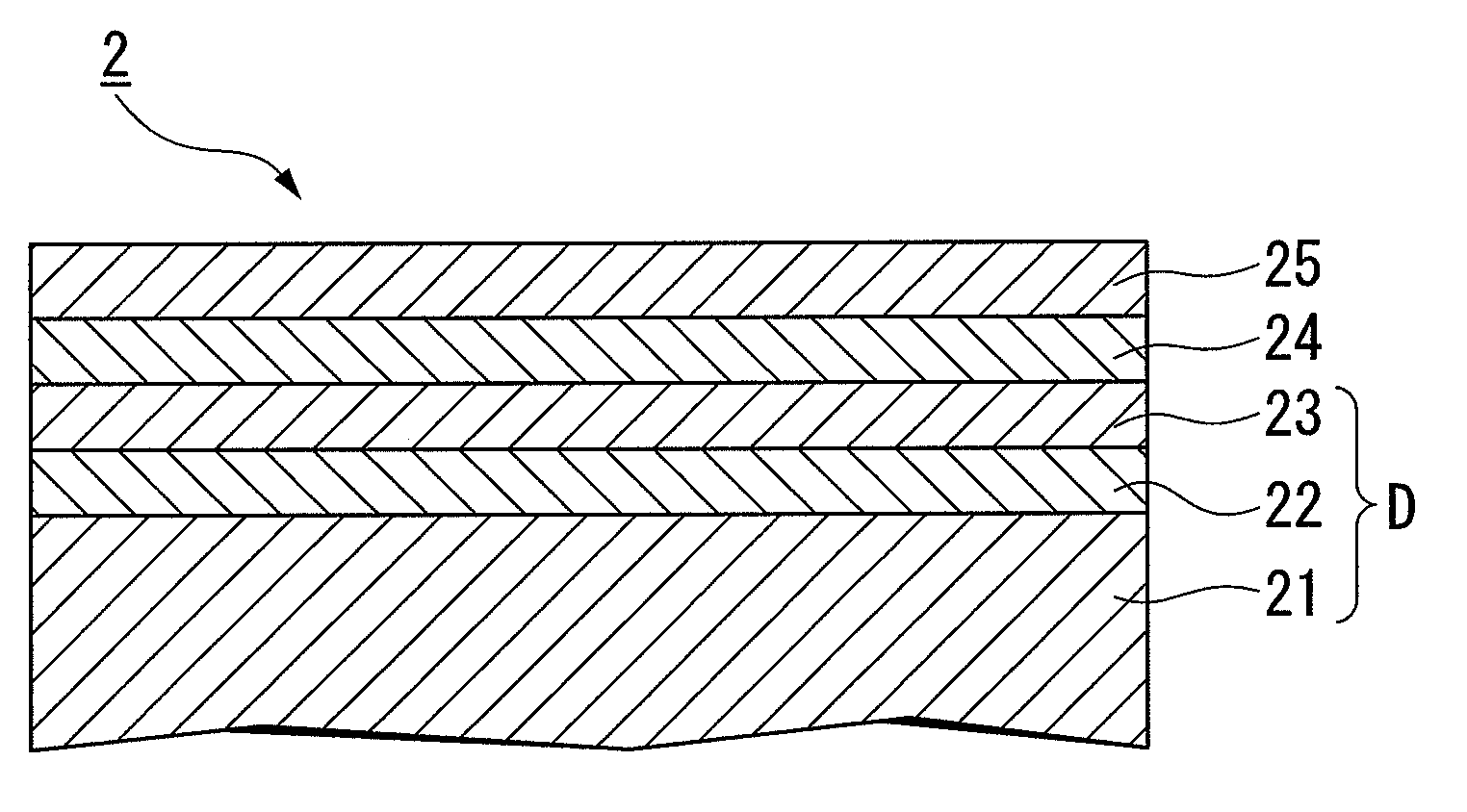
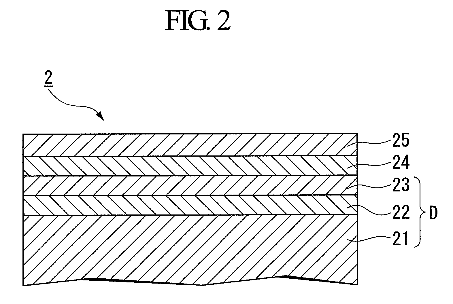
[0131]A non-magnetic substrate 21 which was composed of a NiP-plated aluminum substrate and which was subjected to a texturing treatment using an alumina slurry so as to have a surface roughness Ra of 20 Å was set in a chamber 30 of a sputtering film formation device 3 (a DC magnetron sputtering device) like that shown in FIG. 3. After evacuating the chamber 30 to an ultimate vacuum of 2×10⁻⁴ Pa, a 400 Å thick non-magnetic undercoat film 22 made of Cr and a magnetic film 23 made of a Co82Cr15Ta3 (atomic %) alloy were sequentially formed on both surfaces of the non-magnetic substrate 21 to obtain a substrate D.
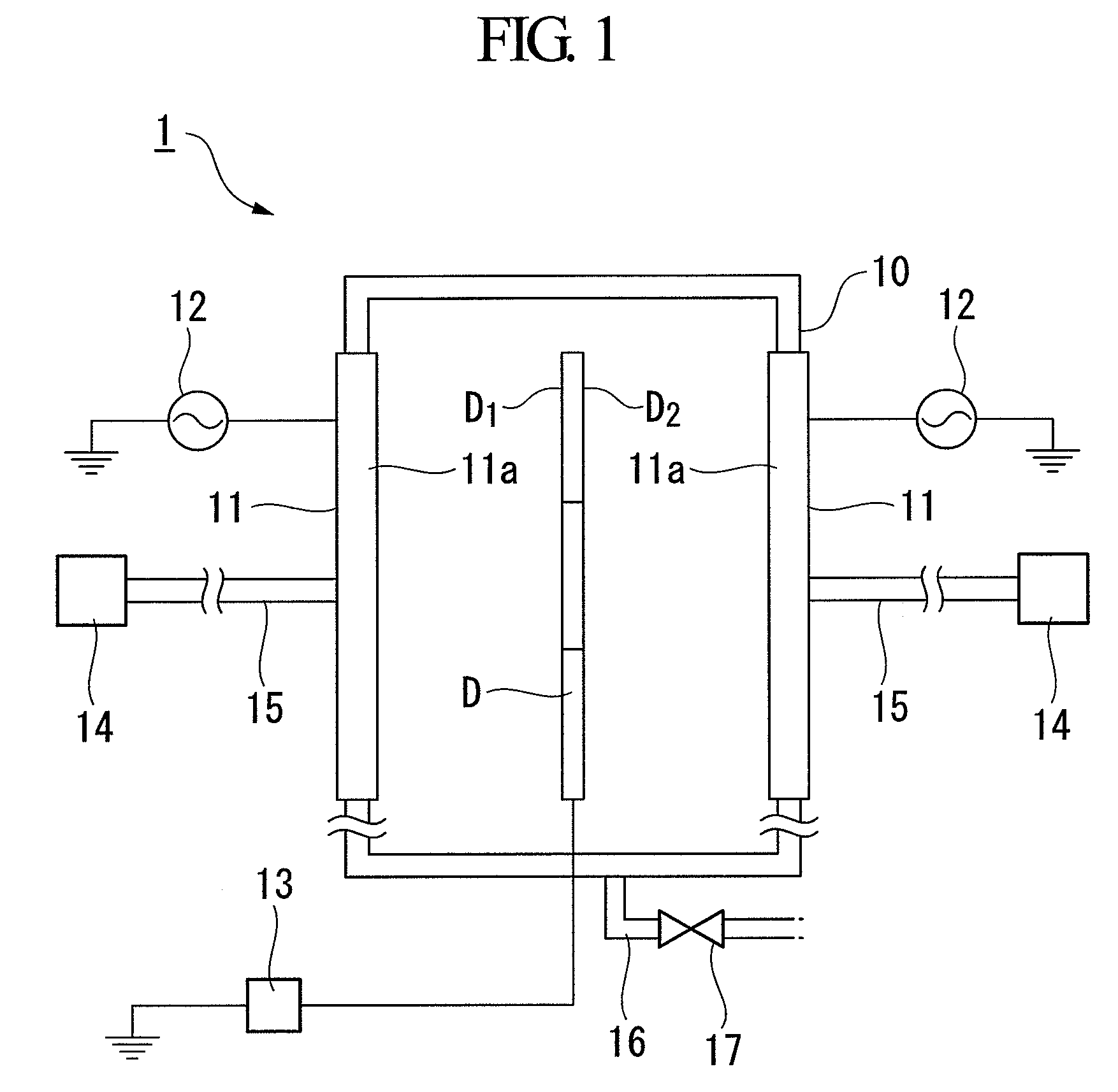
[0132]Next, the substrate D was carried into a film formation chamber 10 of a film formation device 1 (plasma CVD apparatus) like that shown in FIG. 1. The electrodes 11 of the film formation device 1 are made of SUS3O4 and the surface roughness Ra was adjusted to 8.5 μm by subjecting the surface 11a to a sandblasting treatment using SiC particles #20-#30.
[0133]Next, a reacting...
example 2
[0137]A non-magnetic substrate 21 which was composed of a NiP-plate-d aluminum substrate and which was subjected to a texturing treatment using an alumina slurry so as to have a surface roughness Ra of 20 Å was set in a chamber 30 of a sputtering film formation device 3 (a DC magnetron sputtering device) like that shown in FIG. 3. After evacuating the chamber 30 to an ultimate vacuum of 2×10⁻⁴ Pa, a 400 Å thick non-magnetic undercoat film 22 made of Cr and a magnetic film 23 made of a Co82Cr15Ta3 (atomic %) alloy were sequentially formed on both surfaces of the non-magnetic substrate 21 to obtain a substrate D.
[0138]Next, the substrate D was carried into a film formation chamber 10 of a film formation device 1 (plasma CVD apparatus) like that shown in FIG. 1. The electrodes 11 of the film formation device 1 are made of SUS304 and the surface roughness Ra was adjusted to 8.5 μum by subjecting the surface 11a to a sandblasting treatment using SiC particles #20-#30.
[0139]Next, a reacti...
PUM
| Property | Measurement | Unit |
|---|---|---|
| surface roughness Ra | aaaaa | aaaaa |
| surface roughness | aaaaa | aaaaa |
| thickness | aaaaa | aaaaa |
Abstract
Description
Claims
Application Information
 - R&D
- Intellectual Property
- Life Sciences
- Materials
- Tech Scout
- Unparalleled Data Quality
- Higher Quality Content
- 60% Fewer Hallucinations
Browse by: Latest US Patents, China's latest patents, Technical Efficacy Thesaurus, Application Domain, Technology Topic, Popular Technical Reports.
© 2025 PatSnap. All rights reserved.Legal|Privacy policy|Modern Slavery Act Transparency Statement|Sitemap|About US| Contact US: help@patsnap.com


