
System and method for realizing network synchronization by packet network

a network synchronization and packet network technology, applied in the field of communication, can solve the problems of failure to meet the requirement of circuit service, cannot guarantee the transmission delay or the transmission sequence of packets, and achieve the effect of high bandwidth of the ip packet network

Inactive Publication Date: 2008-07-17
HUAWEI TECH CO LTD
View PDF5 Cites 5 Cited by
  • Summary
  • Abstract
  • Description
  • Claims
  • Application Information

AI Technical Summary

Benefits of technology

[0005]Currently, an optional technical solution for network synchronization over an IP packet network is that a synchronization timing network is built together with the IP packet network in order to implement provision of circuit service over the IP packet network, and a method of superposition is adopted to meet requirement on network synchronization.

Problems solved by technology

The other type is a connectionless IP packet network which provides Internet data service and does not strictly guarantee the transmission delay or the transmission sequence of packets.
However, the existing IP network is still a connectionless network without synchronization.
When service of Best effort is provided, in some aspects, especially in respect of synchronization timing throughout the network, requirement on circuit service can not be met.
However, these solutions fail to solve essentially the problem of provision of timing throughout the IP packet network and pose to the contrary a high requirement on the network, which includes a transmission delay over the network, a packet loss ratio over the network.
The deterioration of any index may have deadly influence on the above solutions.
A synchronization network has to be built newly in the existing solution, which results in a drawback of a high network building cost.
Further, a data network and a circuit network have not been unified completely in the existing solution, which results in relatively difficult maintenance operations.

Method used


Image

  • System and method for realizing network synchronization by packet network
  • System and method for realizing network synchronization by packet network
  • System and method for realizing network synchronization by packet network

Examples


first embodiment

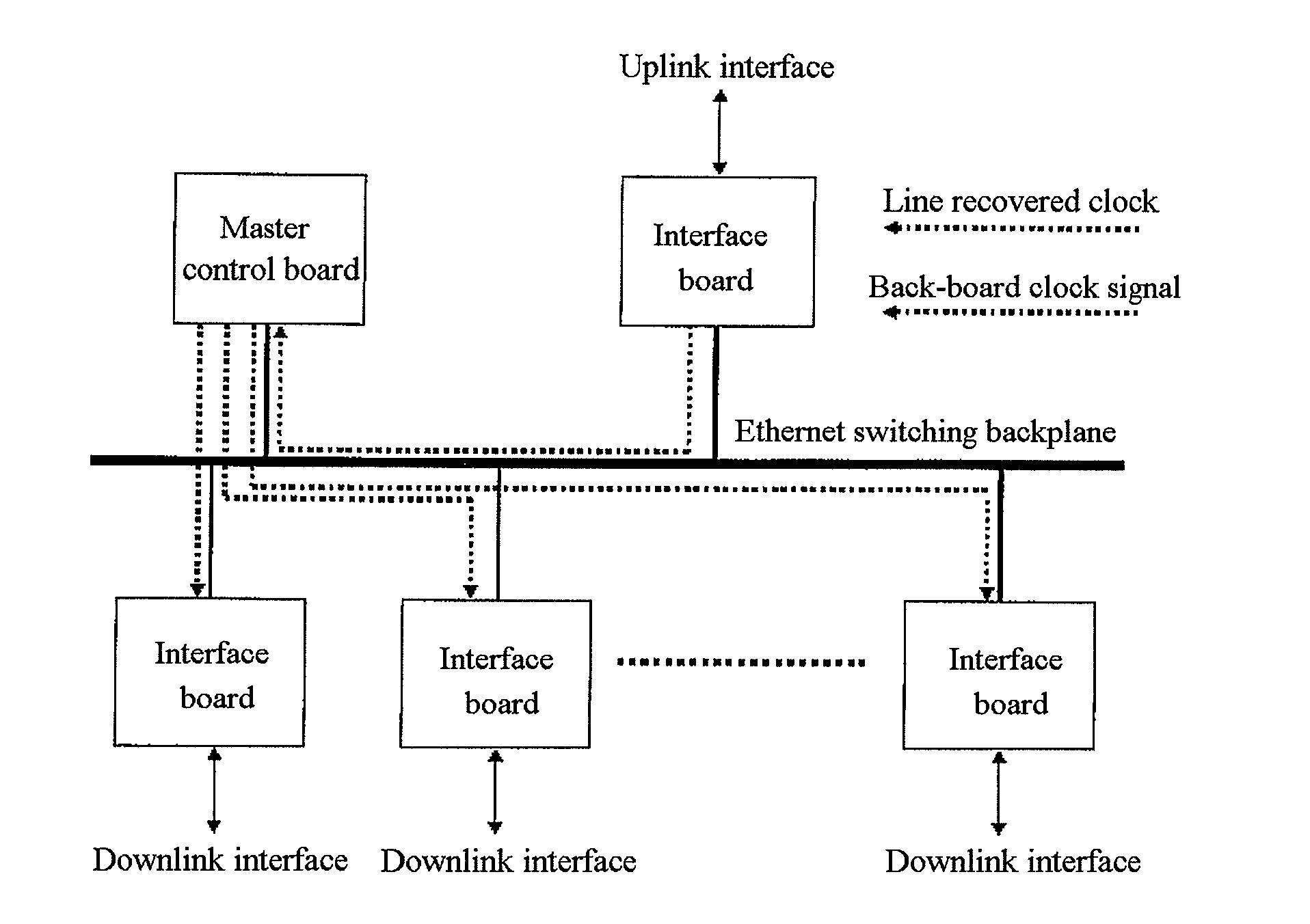
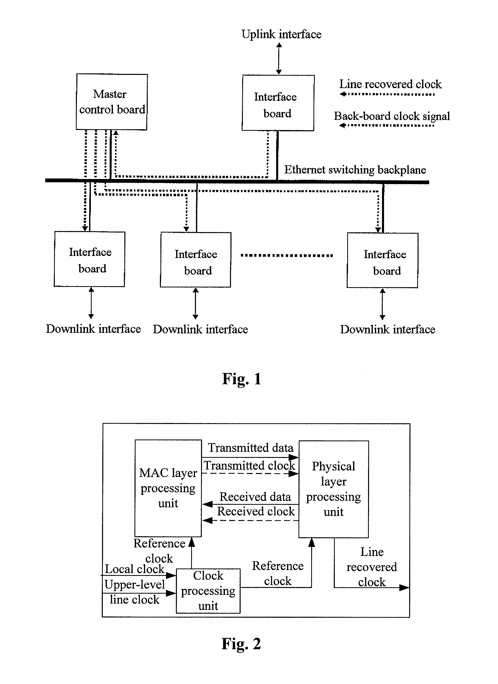
[0042]According to the present invention, the framework of a network device capable of IP synchronization is illustrated in FIG. 1. The network device may be one of a plurality of processing devices at different levels, and the processing device includes a transmission module and a reception module. The transmission module may be provided in a downlink interface board, and the reception module may be provided in an uplink interface board. A switching backplane and a master control board may be provided between the uplink interface board and the downlink interface board. Particularly, the switching backplane may be an Ethernet switching backplane or other IP packet network switching backplanes.

[0043]The uplink interface board exchanges data with a processing device at upper-level over a data link via an interface of the uplink interface board. When data is required to be received from the processing device at upper-level, the uplink interface board recovers a clock signal from the da...

second embodiment

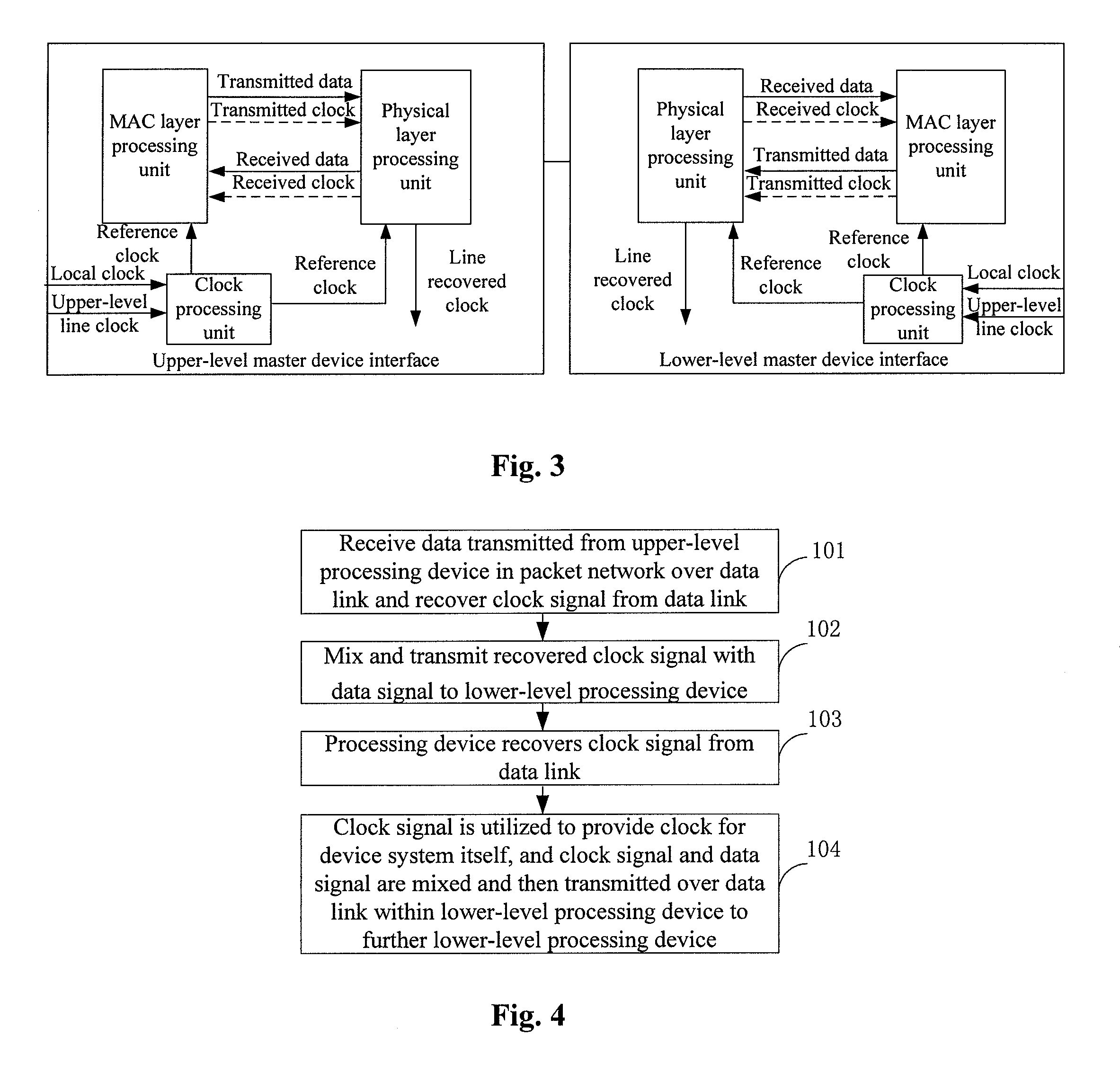
[0063]A method according to the present invention is illustrated in FIG. 4.

[0064]Block 101: In a processing device, Data transmitted from a processing device at upper-level in a packet network is received over a data link and a clock signal is recovered from the data link.

[0065]Block 102: In the processing device, the recovered clock signal and the data signals are mixed and then the mixed signals are transmitted to a processing device at lower-level.

[0066]Block 103: The lower-level processing device recovers the clock signal from the data link.

[0067]Block 104: The clock signal is adaptable to be provided for a clock signal for the processing device at lower-level system itself. The processing device at lower-level mixes the clock signal and the data signals and transmits the mixed signals over a data link to a processing device at further lower-level.

[0068]The processing device at further lower-level proceeds with the block 103.

[0069]An implementation procedure according to the sec...


PUM


Abstract

A system and method for realizing network synchronization by packet network mainly includes: restoring the clock signal from the superior processing equipment data link of the packet network, and sending it to the subordinate processing equipment; realizing the synchronization of said processing equipment based on said clock signal. It can realize the uniform timing of the whole network and change the IP network without the timing into the synchronous network, which is similarly with the circuit network, with high bandwidth. It can not only provide a circuit simulation service, but also a multi-service with high bandwidth.

Description

CROSS-REFERENCE TO RELATED APPLICATIONS[0001]This application is a continuation of International Patent Application No. PCT / CN2006 / 002130, filed Aug. 22, 2006, which claims priority to Chinese Patent Application No. 200510093014.3, filed Aug. 24, 2005, both of which are hereby incorporated by reference.FIELD OF THE INVENTION[0002]The present invention relates to the communication field and in particular to a method and system for network synchronization over a packet network.BACKGROUND OF THE INVENTION[0003]Existing networks can generally be divided into two major types. One type is a synchronized circuit domain network which currently provides telephone service and can strictly guarantee a transmission delay and a transmission sequence of the service through synchronization timing throughout the network. The other type is a connectionless IP packet network which provides Internet data service and does not strictly guarantee the transmission delay or the transmission sequence of pac...

Claims


Application Information

Patent Timeline
IPC IPC(8): H04J3/06
CPCH04J3/0697H04J3/0673
Inventor QU, ZHIJUN
Owner HUAWEI TECH CO LTD
Learn More