Rotatable multi-operation tool for chip removing machining, and a basic body therefor

Inactive Publication Date: 2008-07-17
SANDVIK INTELLECTUAL PROPERTY AB
View PDF33 Cites 34 Cited by
  • Summary
  • Abstract
  • Description
  • Claims
  • Application Information

AI Technical Summary

Benefits of technology

[0011]Yet another object of the invention is to provide a tool by which holes can be recessed having most varying diameters, and simultaneously allow forming of one or more threads of varying profile as well as varying pitch. In a particular respect, the invention aims at increasing the flexibility of the tool so far that the same should be convertible in a simple way for other tasks than thread forming, e.g., pure drilling or hole making. Although the main object of the invention is to provide a

Problems solved by technology

However, a disadvantage of this tool is that the tool has to be discarded, or possibly be reground, as soon as either the front, hole-making cutting edges or the thread-cutting teeth behind have been worn out or otherwise become unusable, because the cutting edges as well as the teeth are integrated in a common, solid drill body.
Another disadvantage is that the tool only can generate threads having a predetermined profile shape and a pr

Method used


Image

  • Rotatable multi-operation tool for chip removing machining, and a basic body therefor
  • Rotatable multi-operation tool for chip removing machining, and a basic body therefor
  • Rotatable multi-operation tool for chip removing machining, and a basic body therefor

Examples


Embodiment Construction

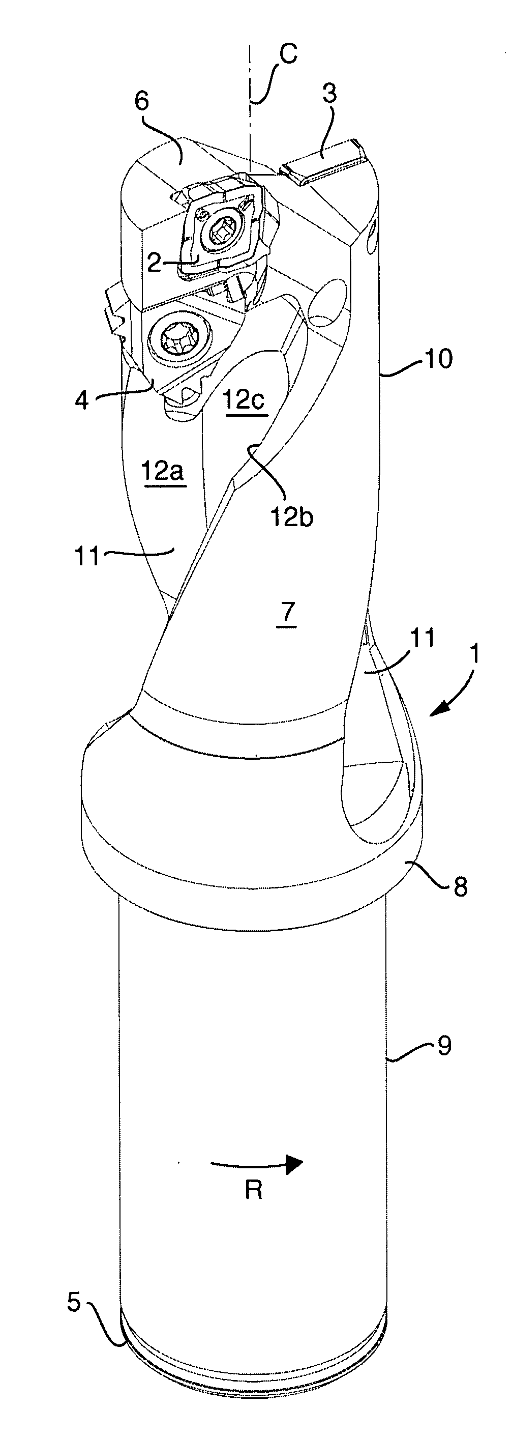
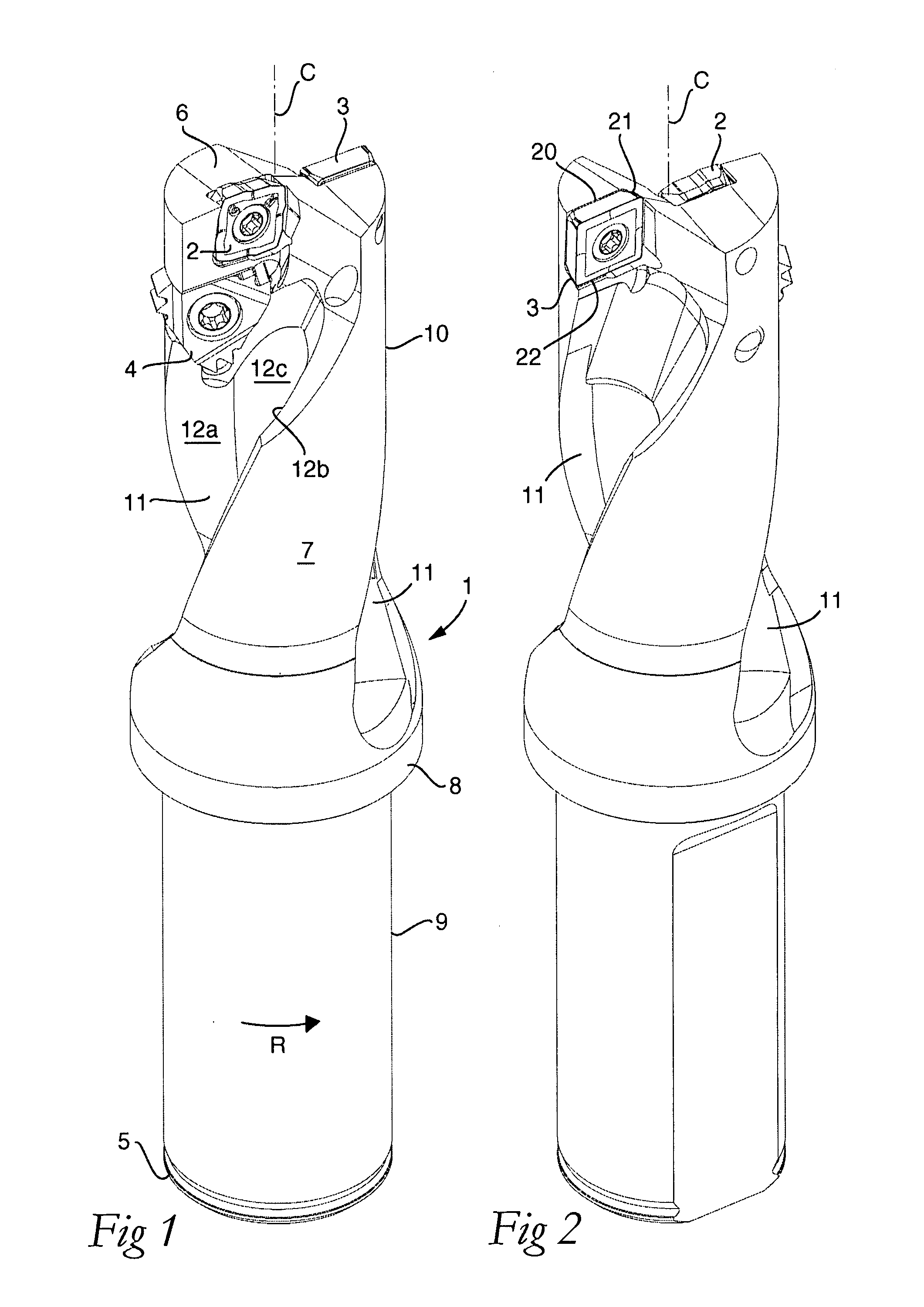
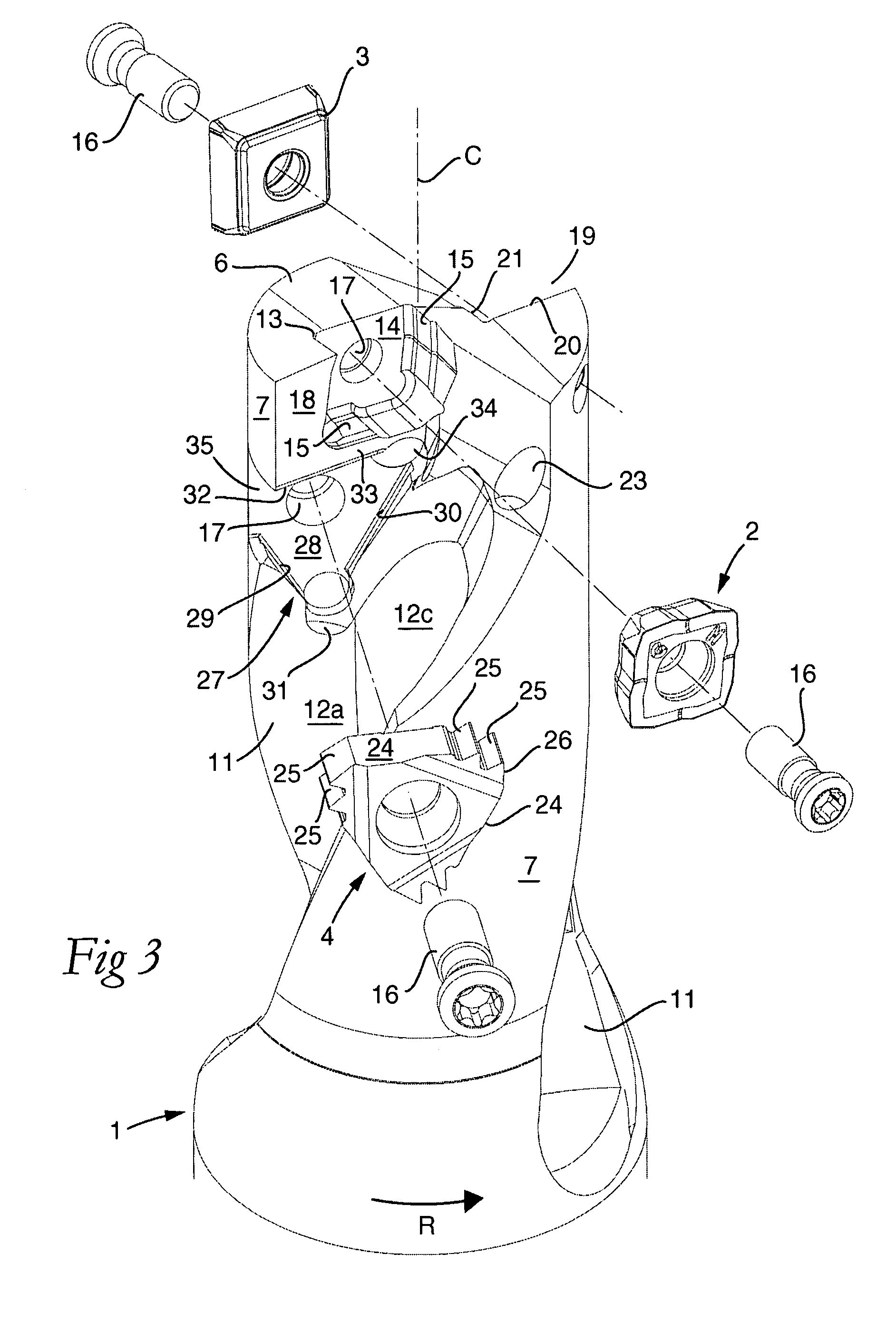
[0029]The tool shown in FIGS. 1-6 includes a basic body 1 as well as a plurality of replaceable cutting inserts 2, 3, 4. The basic body 1 is rotatable in the direction of rotation R around a center axis C and includes a rear end 5 as well as a front end 6, which is formed with a number of part surfaces of limited size. In the backward direction from the front end, an envelope surface 7 extends that in this case is rotationally symmetrical, more precisely cylindrical, and that ends in a collar 8, which separates the envelope surface 7 from a rear fixing part 9 that is fixable in a machine (not shown). In the front part 10 of the drill body delimited by the envelope surface 7, two chip spaces 11 are formed. In the embodiment shown, the basic body 1 has the shape of a drill body, and therefore the chip spaces 11 are flutes having a considerable length. Each flute is helicoidal and has a cross-sectionally concave shape. More precisely, the individual flute is delimited by two side surfa...


PUM

PropertyMeasurementUnit
Angleaaaaaaaaaa
Angleaaaaaaaaaa
Fractionaaaaaaaaaa

Abstract

A rotatable multi-operation tool for chip removing machining, including a plurality of replaceable cutting inserts of different types, and a basic body that is rotatable around a center axis and includes a rear end and a front end from which there is extending rearward an envelope surface in which at least one chip space, delimited by two opposite side surfaces, is countersunk, which opens in the envelope surface and in the front end. A first cutting insert is mounted in a first insert seat that is formed in one side surface of the chip space and situated in the immediate vicinity of the front end and included in a cavity that opens in the front end for the cutting insert to partly protrude axially forward from the front end. A second cutting insert, of a type other than the first cutting insert, is mounted in a second insert seat, which is formed in the same side surface as the first insert seat and situated axially behind the first insert seat. The second insert seat is included in a cavity that opens in a part of the envelope surface.

Description

[0001]This application claims priority under 35 U.S.C. § 119 to Swedish Patent Application No. 0700112-6, filed on Jan. 17, 2007, which is incorporated by reference herein in its entirety.FIELD OF THE INVENTION [0002]The present invention relates generally to a rotatable multi-operation tool for chip removing machining, among other things hole making, of the type that includes, on one hand, a plurality of replaceable cutting inserts of different types, and on the other hand a basic body that is rotatable around a center axis and includes a rear end and a front end from which there is extending rearward an envelope surface in which at least one chip space, delimited by two opposite side surfaces, is countersunk. The chip space opens not only in the envelope surface but also in the front end. A first cutting insert is mounted in an insert seat that is formed in one side surface of the chip space as well as situated in the immediate vicinity of the front end and included in a cavity th...

Claims


Application Information

Patent Timeline
IPC IPC(8): B27G15/00B26D1/12
CPCB23B29/24Y10T408/352B23C5/109B23G5/182B23G5/184B23G2200/10Y10T408/348Y10T408/9097Y10T408/906Y10T407/23Y10T408/90987Y10T407/1906Y10T408/90993Y10T407/2206Y10T407/192B23C3/28B23B51/08B23C3/00B23C5/2204B23C5/2301B23C5/2298
Inventor SJOO, STURE
Owner SANDVIK INTELLECTUAL PROPERTY AB
Why Eureka
Try Eureka