Gasification reactor

a gasification reactor and gasification technology, applied in the direction of gasifier mechanical details, combustible gas production, combustible gas purification/modification, etc., can solve the problems of short life of the refractory lining, damage to the conduit, and sensitive to process upsets

Active Publication Date: 2008-07-24
AIR PROD & CHEM INC
View PDF99 Cites 67 Cited by
  • Summary
  • Abstract
  • Description
  • Claims
  • Application Information

AI Technical Summary

Benefits of technology

[0010]The present invention provides a gasification reactor vessel (1), provided at its upper end with a downwardly directed burner (2), provided with supply conduits for an oxidizer gas (3), a carbonaceous feed (4) and a moderator gas (5), a combustion chamber (6) in the upper half of the vessel, provided with a product gas outlet (7) at its bottom end and an opening for the outlet of the burner (2) at its top end, wherein between the wall of the combustion chamber (6) and the wall of vessel (1) an annular space (9) is provided, and wherein the wall of the combustion chamber comprises an arrangement of interconnected parallel arranged tubes resulting in a substantially gas-tight wall running from a common lower arranged distributor to a higher arranged common header, said distributor provided with a cooling water supply conduit and said header provided with a steam discharge conduit and wherein the steam discharge conduit and the water supply conduit are fluidly connected to a steam drum and wherein the steam drum is provided with a supply conduit for fresh water and wherein the steam drum is positioned at a higher elevation than the common header.

Problems solved by technology

A problem with the above reactors is that the refractory lining has a short life time.
A problem with a water-cooled wall of the combustion chamber is that it is sensitive to process upsets.
For example in case no fresh water is supplied to the cooling conduits overheating will damage the conduits.

Method used


Image

  • Gasification reactor
  • Gasification reactor
  • Gasification reactor

Examples


Embodiment Construction

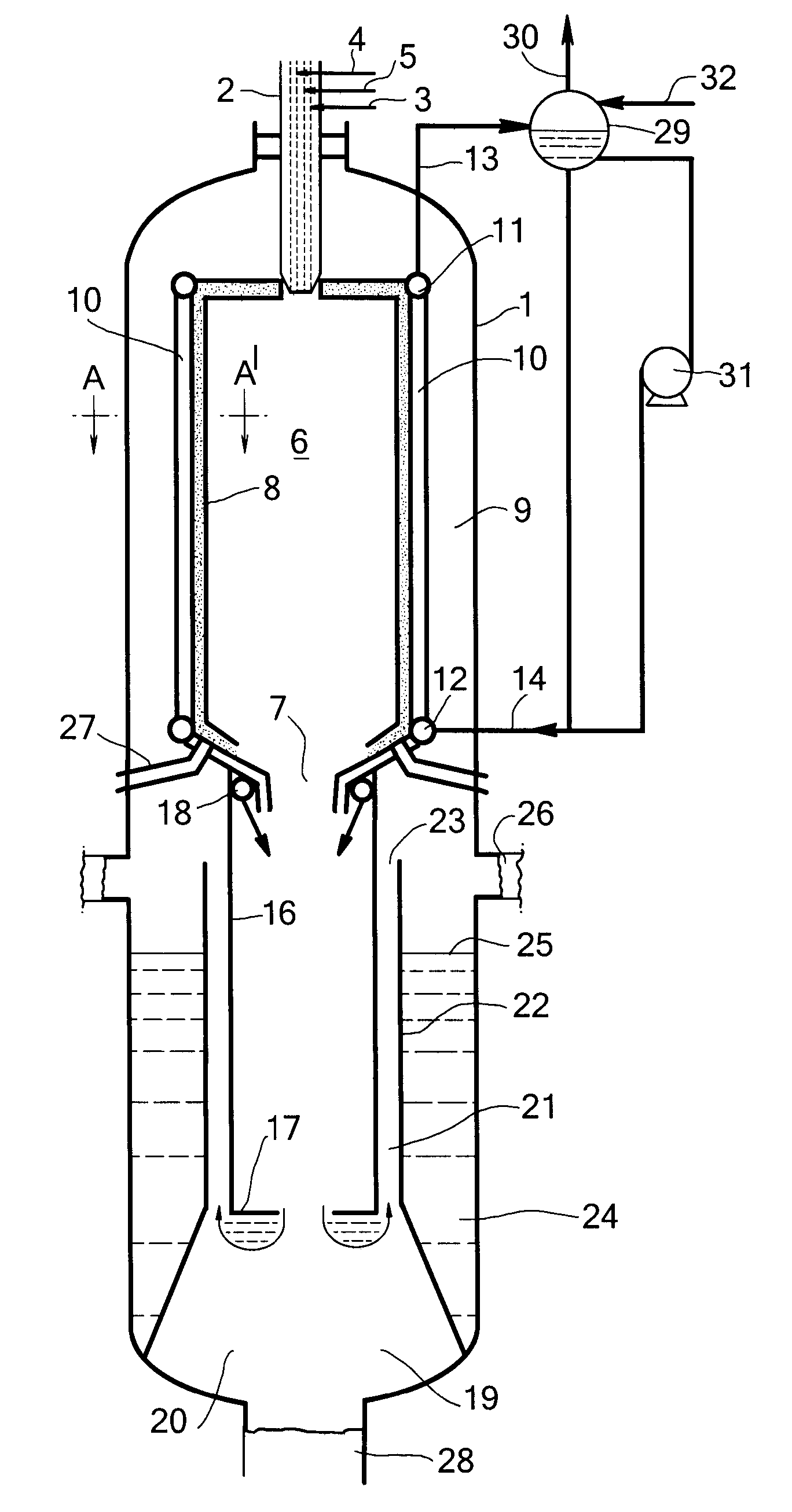
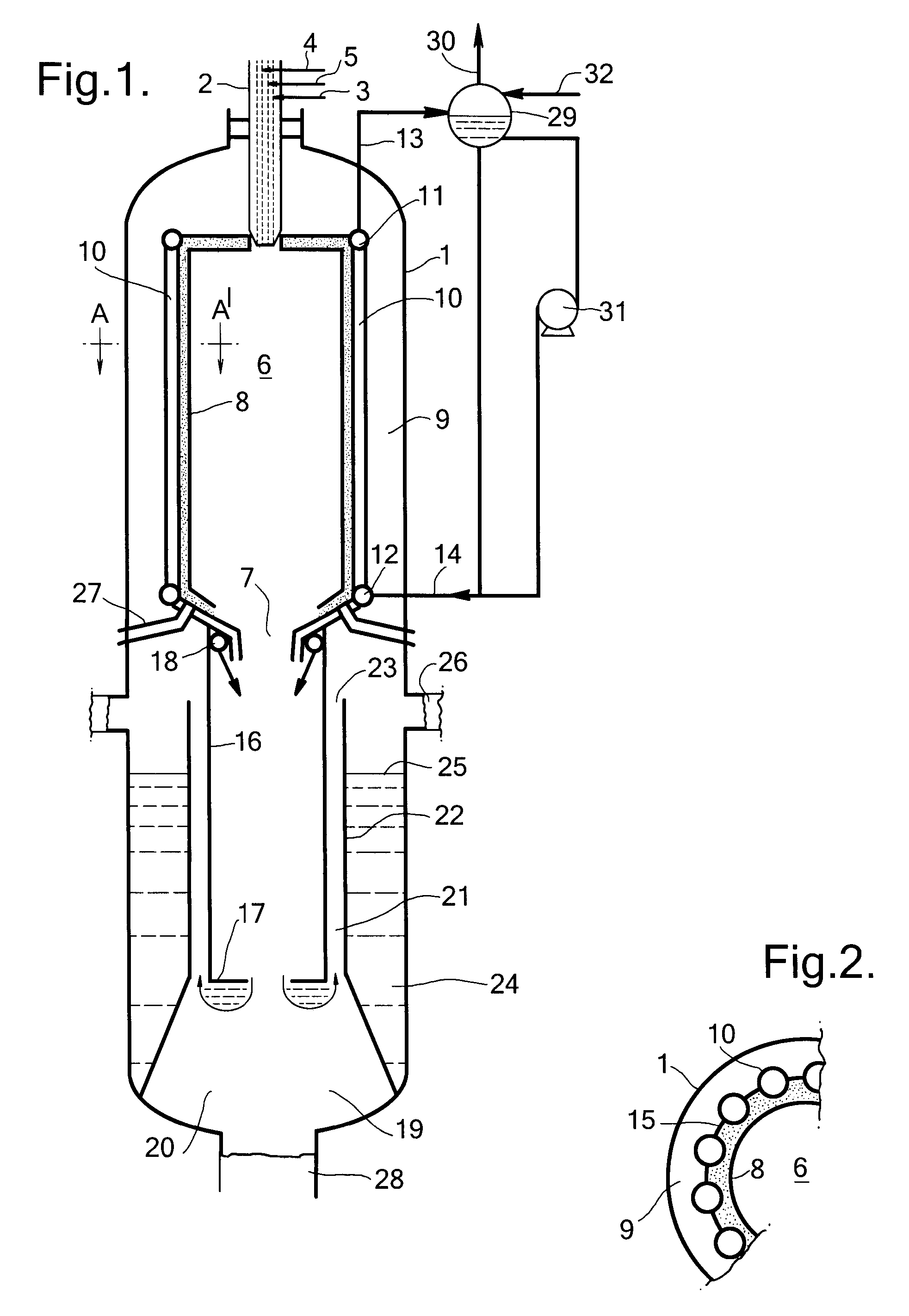
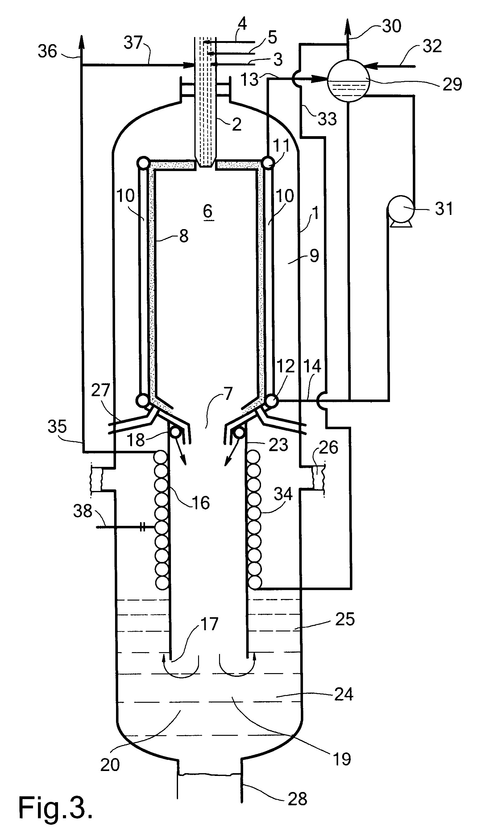
[0014]Applicants found that by cooling the combustion wall with evaporating steam using the apparatus as claimed, a reactor is provided which retains its cooling capacity even in the event that no fresh cooling water is added to the steam drum. Because the steam drum is located at a higher elevation than the common header water as present in the steam drum will flow due to gravity to the common distributor of the gasification reactor. An additional advantage is that steam is produced which can be advantageously used for other applications in a process, which incorporates the gasification reactor. Such applications are process steam for optional downstream shift reactions, heating medium for an optional liquid carbonaceous feed or, after external superheating, as moderator gas in the burner. A more energy efficient process is so obtained.

[0015]The gasification reactor is preferably further provided with water pumping means to enhance the flow of water from the steam drum to the distr...


PUM

PropertyMeasurementUnit
densityaaaaaaaaaa
densityaaaaaaaaaa
densityaaaaaaaaaa

Abstract

A gasification reactor comprising a vessel (1), provided at its upper end with a downwardly directed burner (2), and provided with supply conduits for an oxidizer gas (3), a carbonaceous feed (4) and a moderator gas (5), a combustion chamber (6) in the upper half of the vessel provided with a product gas outlet (7) at its bottom end and an opening for the outlet of the burner (2) at its top end, wherein between the wall of the combustion chamber (6) and the wall of the vessel (1) an annular space (9) is provided, and wherein the wall of the combustion chamber (6) comprises an arrangement of interconnected parallel arranged tubes (10) resulting in a substantially gas-tight wall running from a common lower arranged distributor (12) to a higher arranged common header (11), said distributor (12) provided with a cooling water supply conduit (14) and said header (11) provided with a steam discharge conduit (13) and wherein the steam discharge conduit (13) and the water supply conduit (14) are fluidly connected to a steam drum (29) and wherein the steam drum (29) is provided with a supply conduit (32) for fresh water and wherein the steam drum (29) is positioned at a higher elevation than the common header (11).

Description

[0001]This application claims the benefit of U.S. Provisional Application No. 60 / 868,682 filed Dec. 5, 2006 and European Application No. 06125234.2 filed Dec. 1, 2006, both of which are incorporated by reference.BACKGROUND[0002]The following invention is directed to a gasification reactor vessel, provided at its upper end with a downwardly directed burner, provided with supply conduits for an oxidizer gas, a carbonaceous feed and a moderator gas, a combustion chamber in the upper half of the vessel provided with a product gas outlet at its bottom end and an opening for the outlet of the burner at its top end.[0003]EP-A-168128 describes a gasification reactor provided at its upper end with a downwardly directed burner. The reactor is also provided with a combustion chamber. The combustion chamber is made up from a refractory grade lining. A product gas outlet at the bottom end of the combustion chamber is fluidly connected with a diptube, which diptube is partly submerged in a water ...

Claims


Application Information

Patent Timeline
Patent Type & Authority Applications(United States)
IPC IPC(8): C10J3/26
CPCC10J3/485C10J3/76C10J3/84C10J3/845C10K1/101C10J2200/152C10J2300/093C10J2300/0959C10J2300/1687C10J2200/09
Inventor JANCKER, STEFFENVON KOSSAK-GLOWCZEWSKI, THOMAS PAULWOLFF, JOACHIM
Owner AIR PROD & CHEM INC
Why Eureka
Try Eureka