Evaporative Cooler With Dual Water Inflow

a technology of evaporative cooler and water inflow, which is applied in the direction of machines/engines, lighting and heating apparatus, heating types, etc., can solve the problems of water not evaporated and exiting the pad, and achieve the effect of reducing the number of cycles of water exiting, and reducing the amount of water in the pad

Inactive Publication Date: 2008-07-24
AZ EVAP
View PDF27 Cites 17 Cited by
  • Summary
  • Abstract
  • Description
  • Claims
  • Application Information

AI Technical Summary

Benefits of technology

[0025]This invention is an arrangement of a combination of fluid flow components including flow control valves, spray bars, spray bar orifices, spray bar distribution channels, and distribution caps in a manner that results in a water application profile that is adjusted to match the heat load introduced to the media by the air to be evaporatively cooled. The water evaporation rate is a direct function of this heat load profile. Applying water in this profile takes advantage of the wicking rate and flow through time constant of the evaporative cooling media to effectively distribute the water through the pad. This result in a once through system allows the volume of water being applied to be lowered such that water not evaporated and exiting the pad(s) is limited and does so at very high cycles of concentration while maintaining high levels of cooling effectiveness and scale free pad(s).
[0026]It is therefore a primary object of the present invention to provide an effective water distribution for a once through water metering system using the latest equipment capabilities such that little water beyond that evaporated to cool the air is used while avoiding dry spots and scaling to promote effective cooling.
[0028]Yet another object of the present invention is to distribute water onto evaporative cooling media in a profile that results in very little or no mineral buildup and scale formation to achieve maximum cooling performance.
[0029]Still another object of the present invention is to distribute water onto evaporative cooling media in a profile that results in significantly higher cycles of concentration of water exiting the media to achieve reduced water bleed or discharge requirements and reduce the water withdrawn and used by an evaporative cooler.
[0030]A further object of the present invention is to distribute water onto evaporative cooling media in a profile that results in longer media life by reducing the water passing over the media and washing out the media regifying agents.

Problems solved by technology

This result in a once through system allows the volume of water being applied to be lowered such that water not evaporated and exiting the pad(s) is limited and does so at very high cycles of concentration while maintaining high levels of cooling effectiveness and scale free pad(s).

Method used


Image

  • Evaporative Cooler With Dual Water Inflow
  • Evaporative Cooler With Dual Water Inflow
  • Evaporative Cooler With Dual Water Inflow

Examples


Embodiment Construction

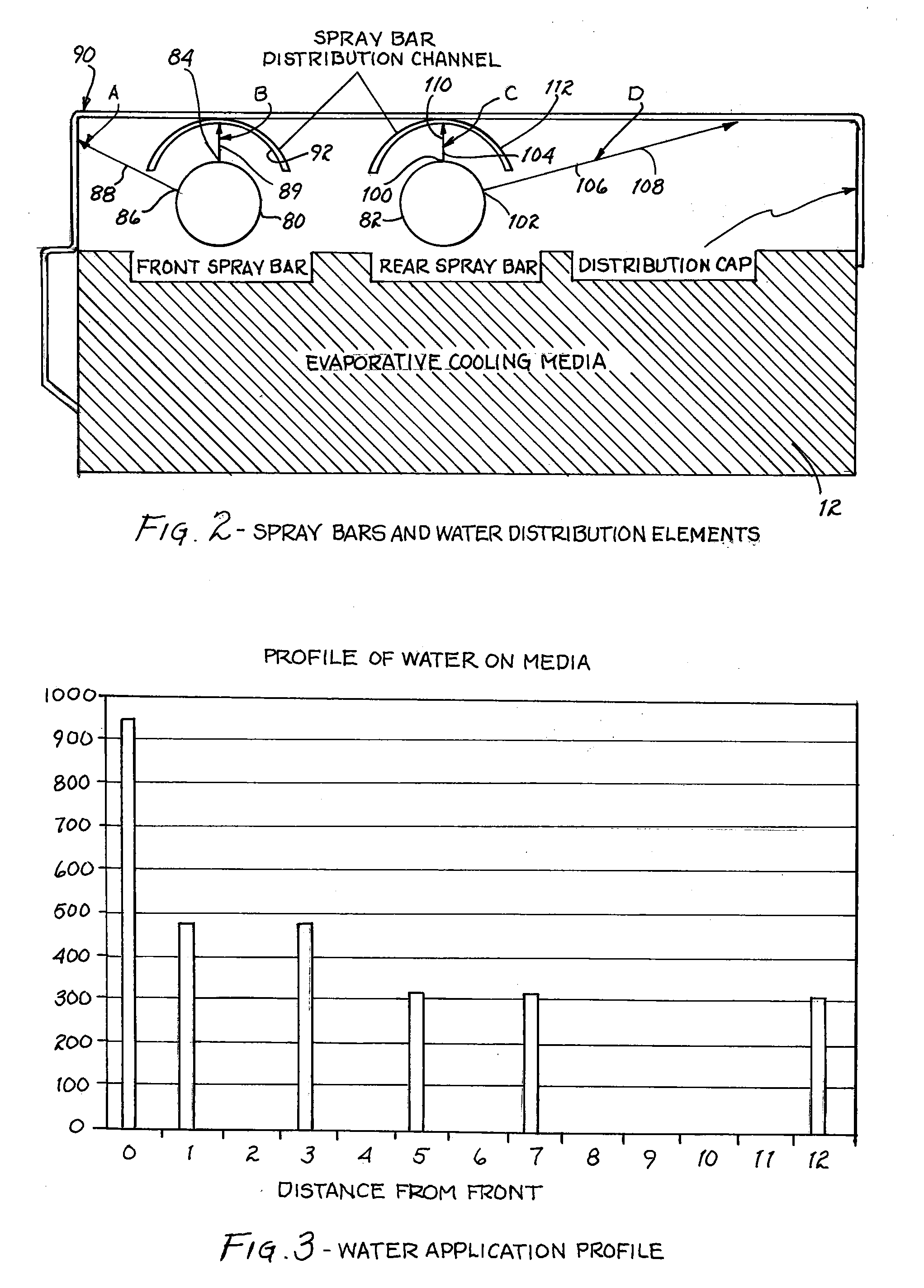
[0035]The psychrometric chart provides that if the inlet dry bulb temperature and the inlet wet bulb temperature are known one can calculate the amount of moisture that can be added to the air and the resulting leaving air dry bulb and wet bulb temperatures for an evaporative cooler. This is known as a mass balance equation. The mass balance equation must be solved for the inlet conditions and the capabilities of the equipment. Further, the rate of water evaporation varies along the air path as it moves through the pad or media and is cooled. This evaporation rate is dependent on the difference between the local conditions and the wet bulb temperature.

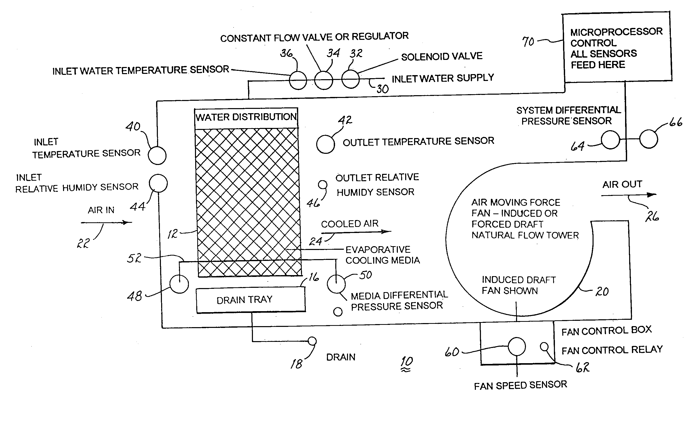
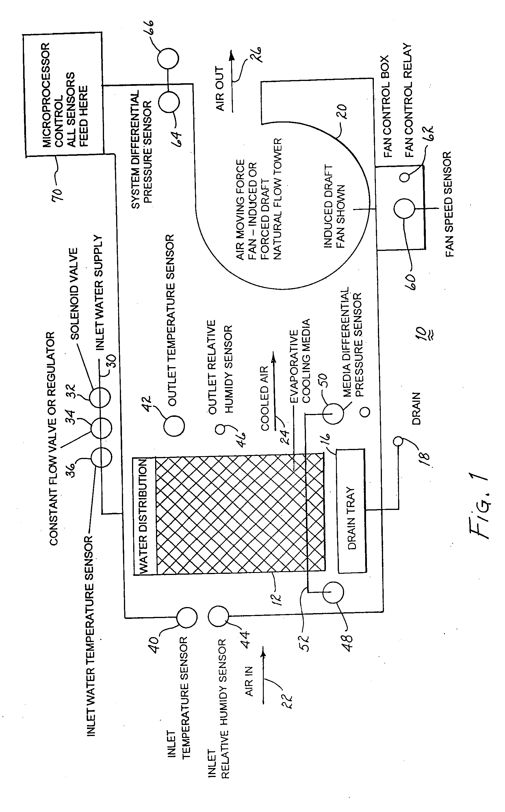
[0036]Existing evaporative coolers attempt to measure the outlet temperature, the pad temperature, and the outlet relative humidity or pad relative humidity. It is known that the physical state of the inlet air drives or is responsible for all efforts to achieve evaporative cooling. At one extreme, if the inlet air is at 100 percent re...


PUM


Abstract

An evaporative cooler includes an arrangement of a combination of fluid components including flow control valves, spray bars, spray bar orifices, spray bar distribution channels, and distribution caps that produce a water application profile on the media that is adjusted to match the heat load introduced to the media by the air to be evaporatively cooled. The water evaporation rate is a direct function of this heat load profile. Applying water in this profile takes advantage of the wicking rate and flow through time constant of evaporative cooling media to effectively distribute the water through the media. This results in a once through system that allows the volume of water being applied be the lowered such that water not evaporated and exiting the media is limited and does so at very high cycles of concentration while maintaining high levels of cooling effectiveness and scale free media.

Description

CROSS REFERENCE TO RELATED PATENT[0001]The present application is related to and claims priority to a provisional application entitled “Evaporative Cooler With Dual Water Inflow” filed Jan. 18, 2007 and assigned Ser. No. 60 / 885,557 and the present application is related to and incorporates by reference the disclosure contained in an application entitled “Water Distribution System For Evaporative Cooler” filed Dec. 21, 2006 and assigned Ser. No. 11 / 569,944.BACKGROUND OF THE INVENTION[0002]1. Field of the Invention[0003]The present invention relates to water distribution systems for evaporative coolers and, more particularly, to a water distribution system for controlling distribution of water uniformly across a media to avoid dry spots, scaling, streaking and distribution of excess water.[0004]2. Description of Related Art[0005]Evaporative cooling appears to be a simple process of passing hot dry air through a wet pad or media to evaporate the water with the latent heat of the air an...

Claims


Application Information

Patent Timeline
Patent Type & Authority Applications(United States)
IPC IPC(8): F28C1/00F28D5/00F24F1/0059
CPCF24F5/0035Y02B30/545F28D5/02F24F2001/0088F28F2025/005F24F1/0007Y02B30/54Y02P80/10F24F1/0059
Inventor KAMMERZELL, DONALD L.KAMMERZELL, LARRY LEE
Owner AZ EVAP
Why Eureka
Try Eureka