
Airframe structure of an aircraft or spacecraft

a technology for aircraft and spacecraft, applied in the field of aircraft or spacecraft airframe structure, can solve the problems of reducing the payload of aircraft, and achieve the effects of reducing the overall strength of the airframe structure, maximizing the utilization of existing construction space, and simplifying the production process

Inactive Publication Date: 2008-07-24
AIRBUS OPERATIONS GMBH
View PDF8 Cites 19 Cited by
  • Summary
  • Abstract
  • Description
  • Claims
  • Application Information

AI Technical Summary

Benefits of technology

The present invention provides an airframe structure for aircraft or spacecraft with a hollow body section that can be sealed off from external pressure. The structure includes a membrane arrangement with at least one multi-curved membrane component for sealing off the internal pressure from external pressure. The membrane arrangement has a receiving well for receiving components of the aircraft or spacecraft. The membrane arrangement is reinforced by at least one brace, which helps reduce stress and allows for a thinner membrane component. The brace can be connected to the membrane arrangement at a connecting region, which can be a weak point in the structure. The connecting region can have a brace or a passage for connecting the interior of the hollow body section to the interior of the receiving well. The invention provides a lighter airframe structure with improved force flux and reduced stresses, leading to a higher payload of the aircraft.

Problems solved by technology

The problem therewith is that the front and rear pressure bulkhead 5 contribute substantially to the aircraft weight and therefore reduce the payload of the aircraft.

Method used


Image

  • Airframe structure of an aircraft or spacecraft
  • Airframe structure of an aircraft or spacecraft
  • Airframe structure of an aircraft or spacecraft

Examples


Embodiment Construction

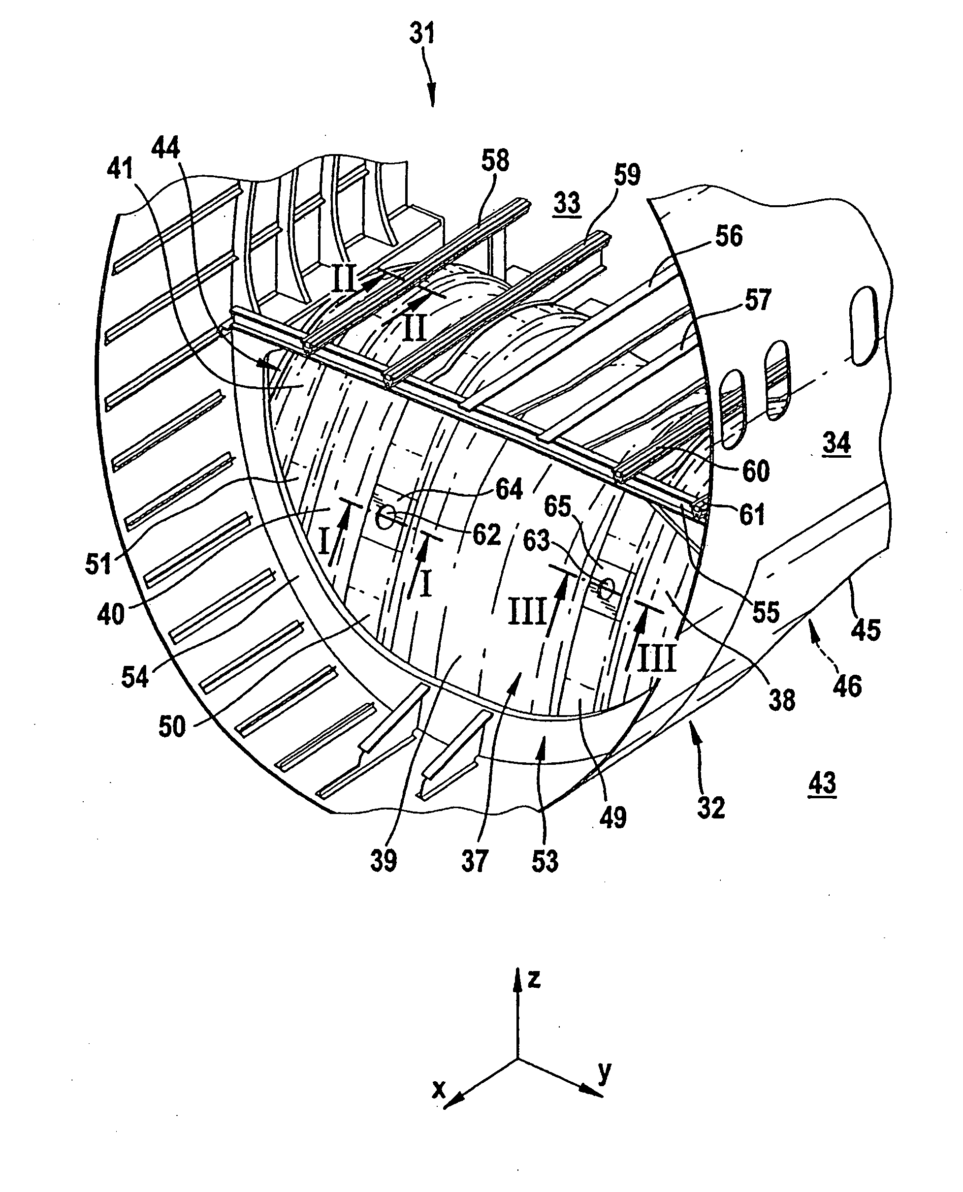
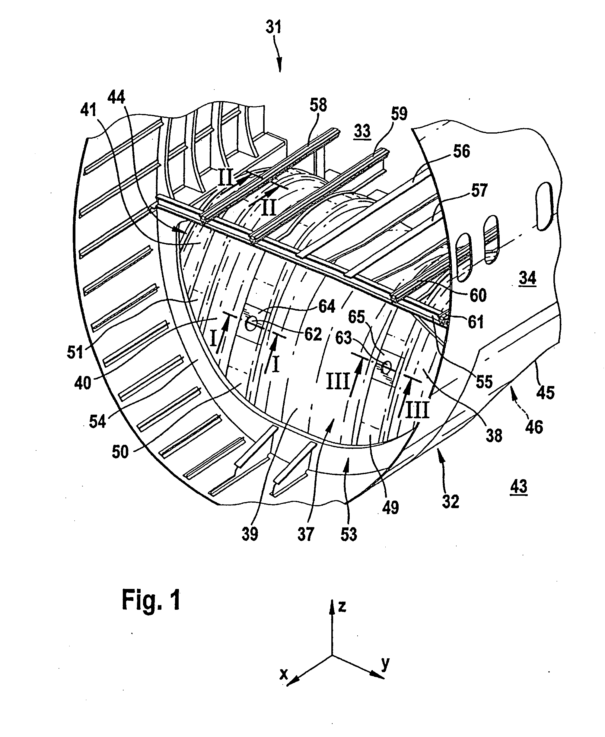
[0036]FIG. 1 shows a perspective view of a section through an airframe structure 31 according to a first exemplary embodiment of the invention.

[0037]The airframe structure 31 has a hollow body section 32 designed as a fuselage shell. The hollow body section 32 has an interior 33 and a skin 34. The interior 33 is under cabin pressure during the flight phase of the aircraft.

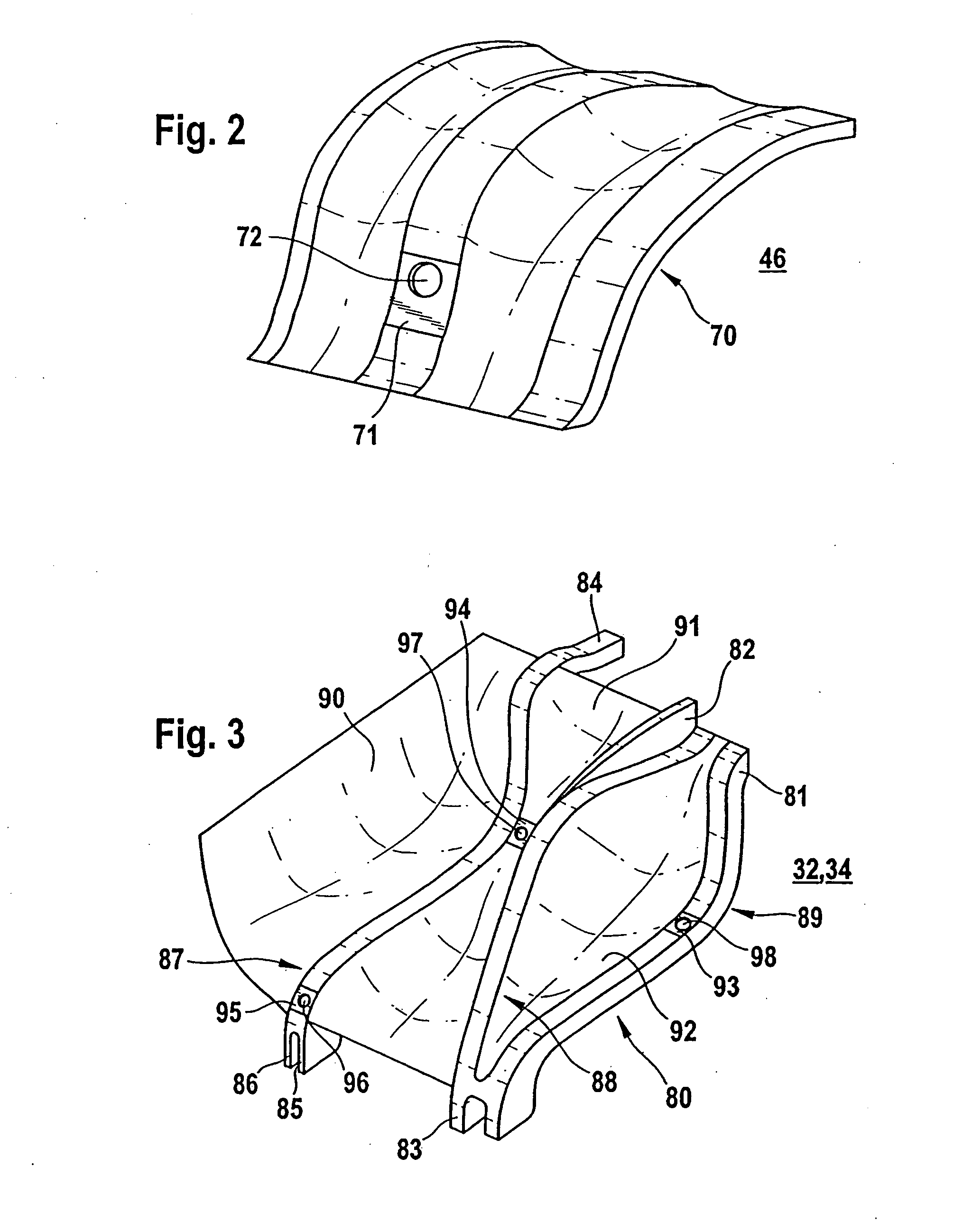
[0038]A membrane arrangement 37 is arranged within the hollow body section 32. The membrane arrangement 37 is divided into preferably a plurality of membrane components 38, 39, 40, 41, preferably into between 2 and 21 membrane components. The membrane components 38 . . . 41 are each designed as single-part, doubly curved, sheet-like elements, preferably made of carbon fibre composite material. The membrane components ensure that the internal pressure is sealed off from the atmospheric external pressure acting in the surroundings 43 of the airframe structure 31. Furthermore, a joining structure 44 is provided which ...


PUM


Abstract

The present invention provides an airframe structure of an aircraft or spacecraft, with: a hollow body section which can be subjected to an internal pressure; a membrane arrangement which has at least one single-part, multi-curved membrane component for sealing off the internal pressure from an external pressure which acts on the hollow body section and differs from the internal pressure; and a joining structure for a pressuretight joining of the membrane arrangement to a region of the hollow body section; wherein the membrane arrangement forms a receiving well which is accessible from outside the hollow body section, extends at least partially into the hollow body -section and is for receiving a component of the aircraft or spacecraft.

Description

FIELD OF THE INVENTION[0001]The present invention is concerned with an airframe structure of an aircraft or spacecraft.BACKGROUND OF THE INVENTION[0002]Although applicable to any airframe structures, the present invention and the problem on which it is based are explained in more detail with reference to a landing gear well in an aircraft fuselage.[0003]In order to explain the general problem, FIG. 5 shows, in a perspective view, a section through an aircraft fuselage section 1 which has a landing gear well 2. The landing gear well 2 has essentially two functions:[0004]First of all, the landing gear well 2 serves to accommodate the landing gear 3 during the flight phase. For this purpose, after the aircraft has taken off, the landing gear 3 is retracted from a deployed position into a retracted position, with essential parts of the landing gear 3, in particular the wheels, projecting into the landing gear well 2.[0005]In the event of a difference in pressure between the cabin pressu...

Claims


Application Information

Patent Timeline
Patent Type & Authority Applications(United States)
IPC IPC(8): B64G1/22E21B43/00B64C1/00
CPCB64C1/061B64C2001/0072Y02T50/433B64G1/22B64C2001/0081Y02T50/40
Inventor MULLER, MARKUSFIEDLER, LARS
Owner AIRBUS OPERATIONS GMBH
Learn More