Crutch stroller

a technology for strollers and strollers, applied in the field of mobility aids, can solve the problems of limiting exercise activities, prolonging rehabilitation, and none of the devices in the field of wheelchairs can provide the assistance needed for the rehabilitation of weak legs

Inactive Publication Date: 2008-07-24
GEE SR LARRY ELLIS
View PDF13 Cites 30 Cited by
  • Summary
  • Abstract
  • Description
  • Claims
  • Application Information

AI Technical Summary

Benefits of technology

[0025]In accordance with the present invention a mobility assistance aid combining the features of both stability and support, comprising: a sturdy, rigid tubular material having sufficient durability and a predetermined center of gravity with a vertically standing two sided “V” shaped open entry frame in which an individual user stands independently with support assist, wherein selective directional steering and bilateral hand braking is controlled, whereby mobilized body support for an individual with manifested physical limitations and abilities is provided.

Problems solved by technology

Mobility aids as forms of prior art were designed as a means of assisting individuals that experienced decreased leg strength or deformities; however, during the recovery process of these individuals, durable medical equipment companies most often supplied them with either the conventional handheld walker, rolling walker, walking cane, or crutches individually, but none of those devices were capable of supplying the assistance required for the rehabilitation of weak legs when so many other areas of the body needing support was totally neglected.
Originally, these devices were thought to give sufficient stability and support; however, since an adequate sense of balance, strength in the arms, legs, wrists and back areas are also required to operate these devices, the individual using these devices would soon become exhausted and limit their activities of exercise resulting in prolonged rehabilitation.
A walker, as a mobility aid of prior art has stability due to the construction of the base, but since the stability feature of that walker is limited to stabilizing the walker and not the individual user, it is not sufficiently accommodating alone to provide adequate assistance in the mobilization of an individual, whereby the resulting effects generally produced significant postural and back problems or injury due to the lack of proper body alignment and support.
But crutches alone hinder the endurance of the weak, because most of the individuals energy is used lifting the crutches with each step taken.
Dating back as far as the 1800's inventors have made several unsuccessful attempts to combine the advantages of both the walker and crutches; however, during the production of those earlier models such factors as the bulk weight, size of the device, the localized limitations on maneuverability and transportation of the device were not considered for life-styles of today.
Also, the single bilateral support bar member was so close to the rear of the device, that backwards falls would be the inevitable.
Thus, safety was not a feature of that device.
If the user did not have adequate strength this device would be dangerous on declining surfaces, add work load for weakened wrists and arms.
Thereafter, U.S. patent No. 2004 / 0020525 A1 Feb. 5, 2004 to Harry Lev of Youngstown, Ohio created a device with small castors that would present a difficult situation during attempts to mobilize the device on carpet, ruff surfaces, and tilting over the device during maneuvers.
Another danger of this device was instability, due to the hand grip placements being so far to the rear of the upper “U” shaped member, making this device unsafe to operate.

Method used


Image

  • Crutch stroller
  • Crutch stroller
  • Crutch stroller

Examples


Embodiment Construction

—FIGS. 1-6 PREFERRED EMBODIMENT

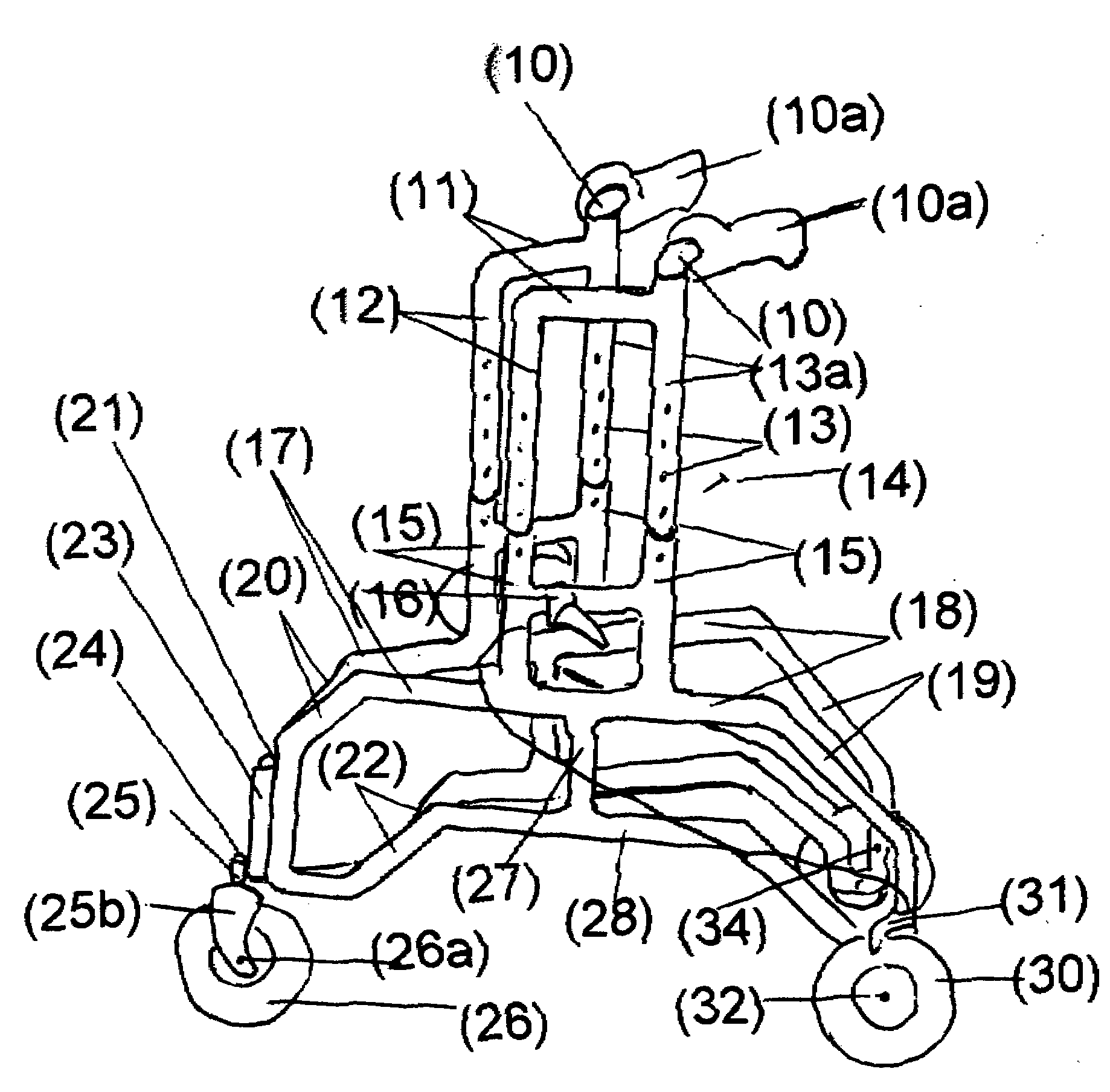
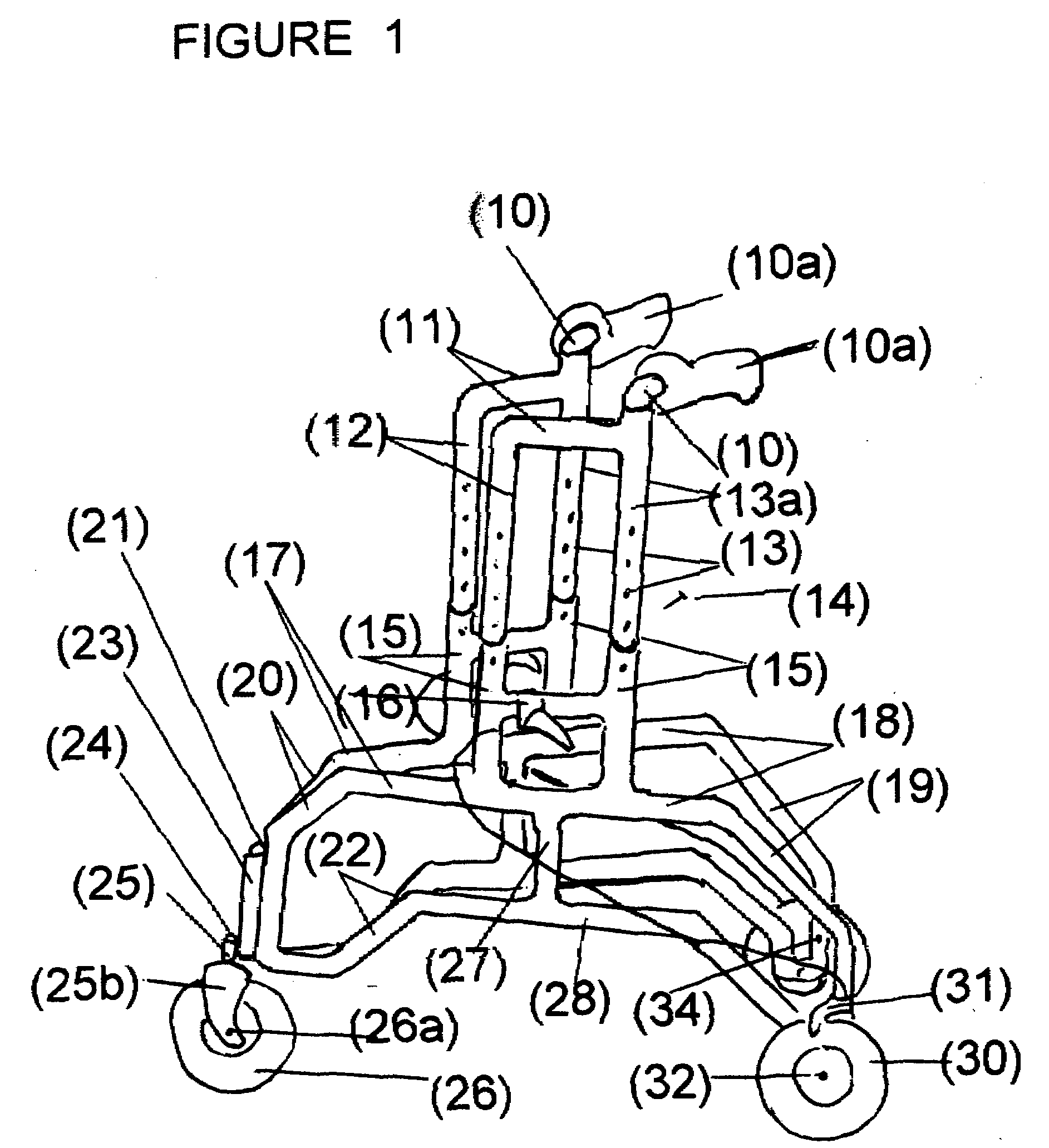
[0033]FIG. 1 Showing a left sided view of the crutch stroller demonstrates from top to bottom 10a, bilateral arm pads adhesively attached to “L” shaped arm pad support bars 10, having the lower end inserted into the upper end of the rear vertical support bars 13a. Bilateral front and rear adjustable vertical support bars 12, 12a, 13, and 13a, are bilaterally connected at the upper surface by horizontal connectors 11, to reinforce the vertical support bars 12, 12a, 13, and 13a. the lower distal ends of the vertical support bars 12, 12a, 13a, being male ends are inserted into the upper female openings of the bilateral risers 15, allowing for the vertical descent of the vertical support bars 12, 12a, 13, and 13a, whereby accommodating the adjustability feature of the vertical supports by the placement of pins 14, into adjustment holes 14a. Each vertical riser 15, is connected front to rear bilaterally by riser connectors 15a, to accommodate a stationary h...


PUM


Abstract

A mobility aid (FIG. 1) design for providing stabilized mobility support by the practical use of a two sided vertically supported rigid frame comprising front and rear bilaterally double support members (12), (12a), (13), (13a), (15), and (15a), and not limited to but preferably of aluminum construction to include a plurality of upper and lower substantially identical bilaterally horizontal and vertical tubular main frame members (17), (18), (19), (20), (22), (27), (28), and (29), supported on a plurality of sufficiently sized wheels (26), and (30), attached to the underside of the main frame (26), and (30), with predetermined spacing. Base members (22), (28), and (29), are sufficiently elevated-providing for unhindered foot movement during mobilization. A guide wheel assembly (23), (25), (25b), (26), and (26a), is vertically attached at a contiguously anterior junction surface of the two sided main frame assembly (20), and (23), thereby providing selective directional steering. Hand brake controls (16), secure by clamps to riser connectors (15), activate brakes (31).

Description

CROSS-REFERENCE TO RELATED APPLICATION[0001]This application claims the benefit of provisional patent application Ser. No. 60 / 885,813 filed Jan. 19, 2007 by the present inventor.FEDERALLY SPONSORED RESEARCH [0002]Not ApplicableSEQUENCE LISTING OR PROGRAM [0003]Not ApplicableBACKGROUND OF THE INVENTION [0004]1. Field of the Invention[0005]The present invention relates to mobility aids, specifically to those used as means to combine the features of both stability and mobilized body support for an individual with manifested physical limitations and abilities that are the results of generalized weakness due to sickness, crippling bone disease, deformities, and post surgical procedures.[0006]2. Prior Art[0007]Mobility aids as forms of prior art were designed as a means of assisting individuals that experienced decreased leg strength or deformities; however, during the recovery process of these individuals, durable medical equipment companies most often supplied them with either the conve...

Claims


Application Information

Patent Timeline
Patent Type & Authority Applications(United States)
IPC IPC(8): A61H3/04
CPCA61H3/04A61H2201/1614A61H2003/046
Inventor GEE, LARRY ELLIS
Owner GEE SR LARRY ELLIS
Why Eureka
Try Eureka