
Multi-stage amplifier with multiple sets of fixed and variable voltage rails

a multi-stage amplifier and variable voltage technology, applied in the field of signal processing, can solve the problems of increasing power loss, increasing the efficiency of the amplification stage, and often insufficient power to drive the output device of the electric signal

Active Publication Date: 2008-07-24
CIRRUS LOGIC INC
View PDF96 Cites 73 Cited by
  • Summary
  • Abstract
  • Description
  • Claims
  • Application Information

AI Technical Summary

Benefits of technology

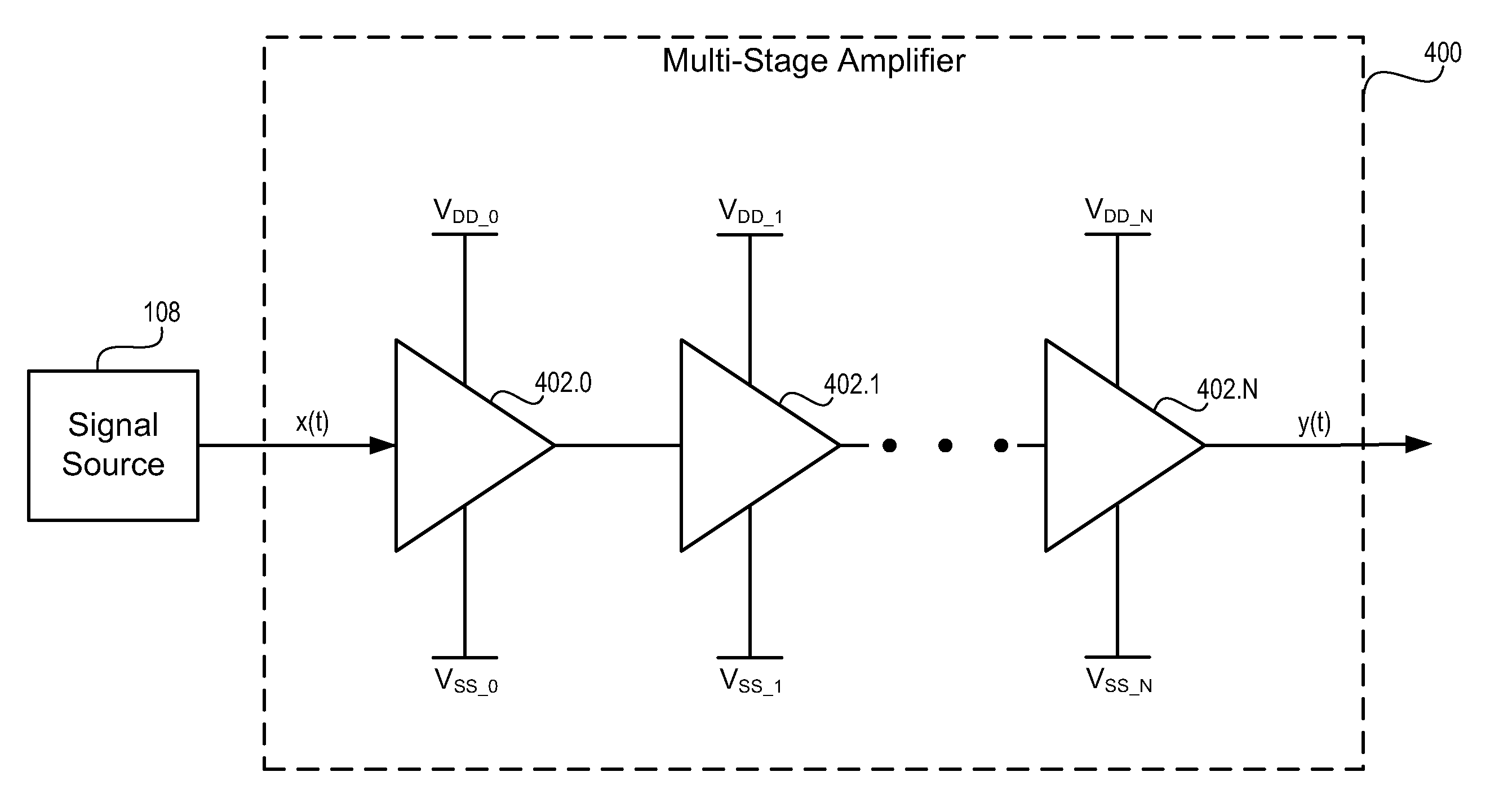
The present invention provides a method and device for amplifying an input signal using a multi-stage amplifier. The invention includes a first amplification stage with a fixed supply voltage and a variable supply voltage, a second amplification stage with a fixed supply voltage and a second variable supply voltage, and a third amplification stage with a fixed supply voltage and a third variable supply voltage. The invention also includes a system where a second amplification stage receives the fixed supply voltage and the second variable supply voltage, and a third amplification stage receives the fixed supply voltage and the first variable supply voltage. The technical effects of the invention include improved amplification of input signals and reduced distortion during amplification.

Problems solved by technology

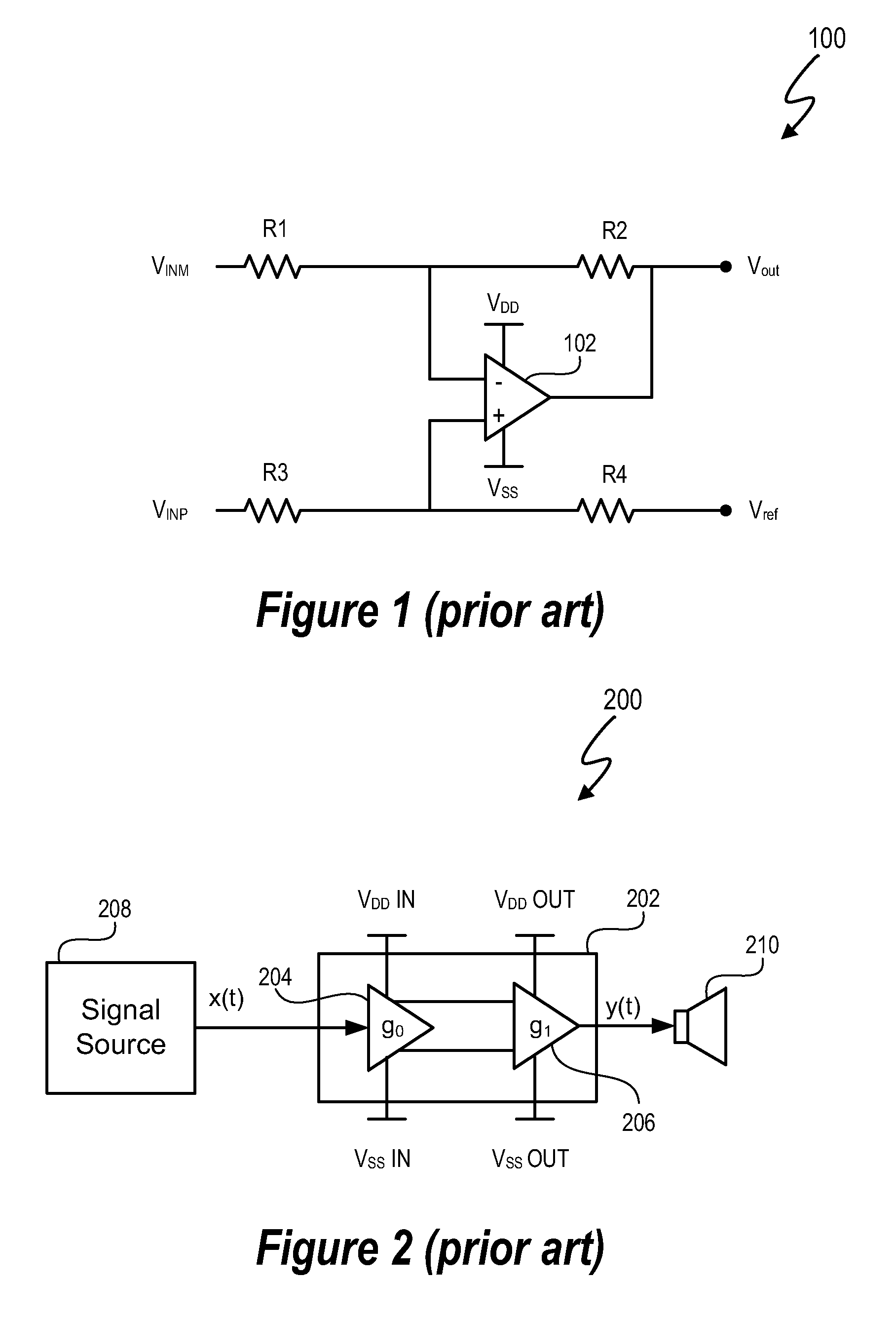
The electrical signal often has insufficient power to drive an output device such as an audio speaker.
Efficiency of an amplification stage, in terms of power loss, increases as a difference between an input signal voltage and voltage rail decreases.

Method used


Image

  • Multi-stage amplifier with multiple sets of fixed and variable voltage rails
  • Multi-stage amplifier with multiple sets of fixed and variable voltage rails
  • Multi-stage amplifier with multiple sets of fixed and variable voltage rails

Examples


Embodiment Construction

[0025]A signal processing system and method utilizes a multi-stage amplifier to amplify an input signal. The multi-stage amplifier uses a mixed set of voltage rails to improve the operating efficiency of at least one of the amplification stages while allowing other amplification stages to operate in a predetermined operating mode. Efficiency of at least one of the stages is improved by providing a different set of the amplifier stages is improved by utilizing at least one variable voltage rail supplied to an amplification stage of the multi-stage amplifier. The variable voltage rail varies in response to changes in an input signal voltage to the amplification stage. For amplifier stages having different voltage supply requirements, the multi-stage amplifier operates with mixed sets of voltage supply rails to allow amplification stage efficiency and provide adequate voltage to allow operation of all amplification stages. Accordingly, at least one amplification stage utilizes a variab...


PUM


Abstract

A signal processing system and method utilizes a multi-stage amplifier to amplify an input signal. The multi-stage amplifier uses a mixed set of voltage rails to improve the operating efficiency of at least one of the amplification stages while allowing other amplification stages to operate in a predetermined operating mode. Efficiency of at least one of the stages is improved by supplying at least one variable voltage rail to an amplification stage of the multi-stage amplifier. The variable voltage rail varies in response to changes in an input signal voltage to the amplification stage. Accordingly, at least one amplification stage utilizes a variable voltage rail, and all amplification stages are supplied with a set of voltage rails that provides sufficient input signal headroom, thus, providing amplification stage efficiency and adequate voltage to allow operation of all amplification stages.

Description

CROSS-REFERENCE TO RELATED APPLICATION[0001]This application claims the benefit under 35 U.S.C. § 119(e) and 37 C.F.R. § 1.78 of U.S. Provisional Application No. 60 / 885,673, filed Jan. 19, 2007 and entitled “Amplifier with Fixed and Variable Supply Rails.” U.S. Provisional Application No. 60 / 885,673 includes exemplary systems and methods and is incorporated by reference in its entirety.BACKGROUND OF THE INVENTION[0002]1. Field of the Invention[0003]The present invention relates in general to the field of signal processing, and more specifically to a system and method for processing signals with a multi-stage amplifier having multiple fixed and variable voltage rails.[0004]2. Description of the Related Art[0005]Many electronic devices utilize one or more amplifiers to amplify an electrical signal. For example, in an audio context, a microphone utilizes transducers to convert sound waves into a corresponding electrical signal. An audio and / or video playback device reads stored data an...

Claims


Application Information

Patent Timeline
Patent Type & Authority Applications(United States)
IPC IPC(8): H03F3/68
CPCH03F1/0222H03F3/187H03F3/45183H03F3/45475H03F2200/03H03F2203/45138H03F2200/405H03F2200/408H03F2200/504H03F2200/516H03F2200/351H03F1/0227H03F3/45H03F3/3001
Inventor TUCKER, JOHN C.PRASAD, AMMISETTI V.
Owner CIRRUS LOGIC INC
Learn More