Steam turbine rotor blade

a technology of steam turbines and rotor blades, which is applied in the direction of liquid fuel engines, marine propulsion, vessels, etc., to achieve the effects of reducing rigidity, increasing the length of steam turbine rotor blades, and reducing vibration characteristics

Inactive Publication Date: 2008-07-24
MITSUBISHI HITACHIPOWER SYST LTD
View PDF4 Cites 11 Cited by
  • Summary
  • Abstract
  • Description
  • Claims
  • Application Information

AI Technical Summary

Benefits of technology

[0022]In accordance with the present invention, it is possible to prevent the reduction of rigidity caused by the increased length of the steam turbine rotor blade and the degradation of vibration characteristics.

Problems solved by technology

It is not necessarily assumed that the related art has provided satisfactory solutions for subjects caused by the increased length of the steam turbine rotor blade.

Method used


Image

  • Steam turbine rotor blade
  • Steam turbine rotor blade
  • Steam turbine rotor blade

Examples


first embodiment

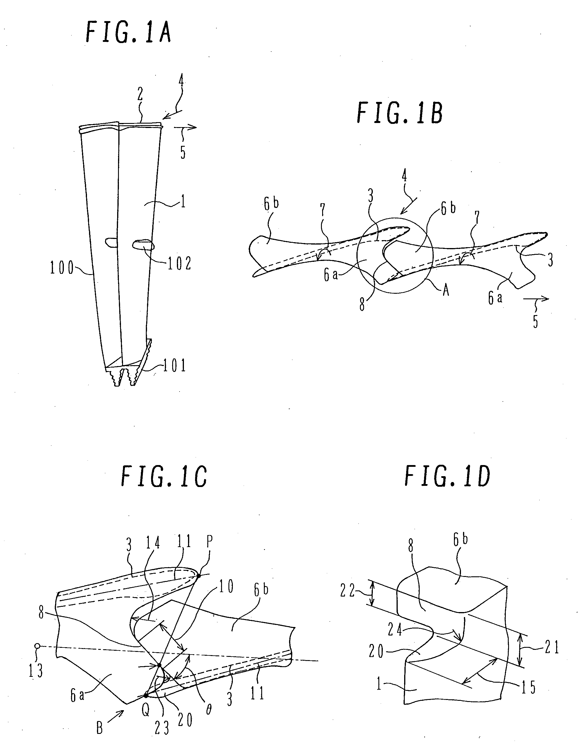
[0042]An embodiment will be explained with reference to FIGS. 1A to 1D.

[0043]As shown in FIG. 1A, a cover 2 integrally formed on a profile 1 is provided at an end of a steam turbine rotor blade (hereinafter referred to as rotor blade) 100.

[0044]An implanting portion 101 for implant the rotor blade 100 into the rotor shaft is formed at the root of the rotor blade 100. A tie-boss 102, i.e., a connecting member for circumferentially connecting a plurality of rotor blades is formed at the central portion of the profile 1.

[0045]It should be noted that, when steam flows in from a steam inflow direction 4, the rotor blade 100 rotates in a rotational direction 5.

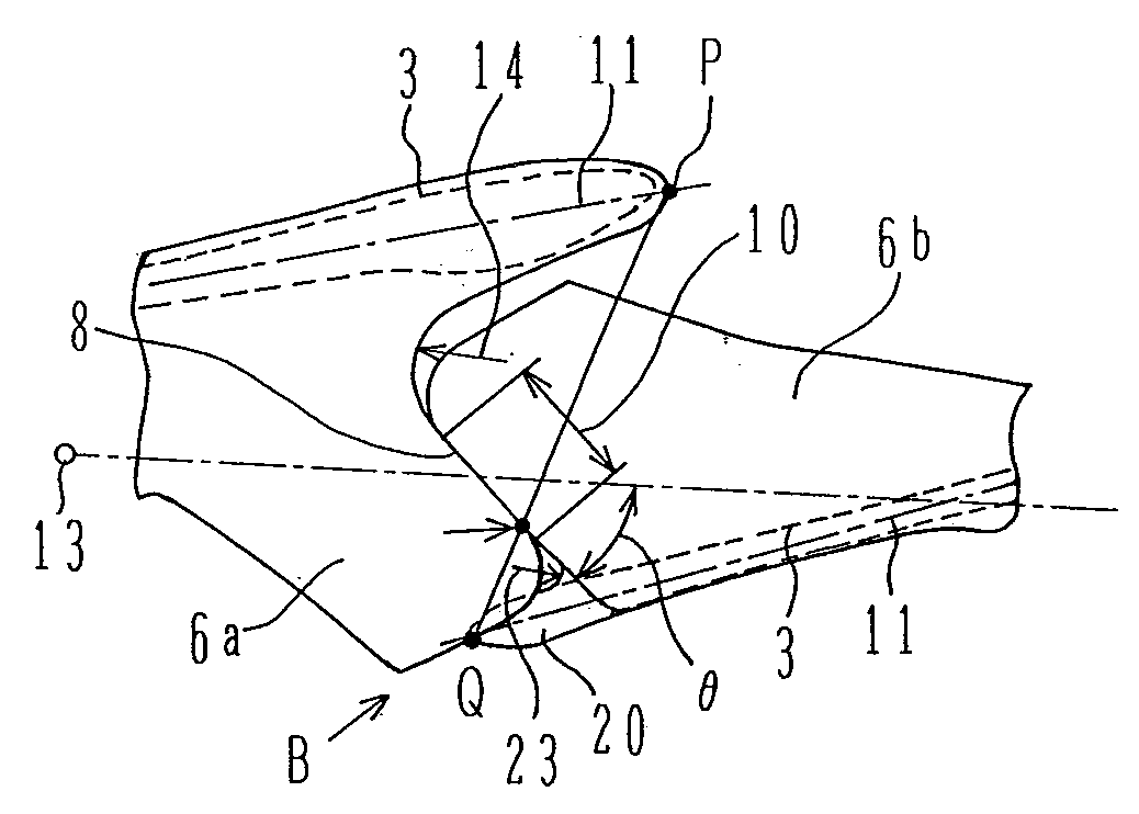
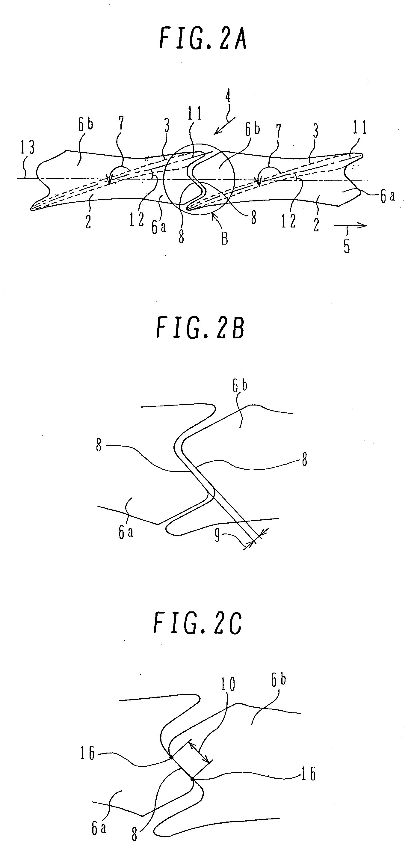
[0046]FIG. 1B is a diagram showing the cover 2 of the rotor blade 100 as viewed radially from the outer circumference side.

[0047]The cover 2 is integrally formed on the profile 1 at an end of the rotor blade 100. FIG. 1B shows a blade condition during rotation. As shown in FIG. 1B, a torsional return force 7 is exerted on the rotor ...


PUM


Abstract

A subject of the present invention is to prevent the reduction of rigidity caused by the increased length of a steam turbine rotor blade and the degradation of vibration characteristics. A steam turbine rotor blade according to the present invention comprises a profile and a cover integrally formed on and at an end of the profile, the leading edge of the cover formed on the profile and the trailing edge of a cover formed on an adjacent preceding profile being in contact and connected with each other by the torsional return force produced during rotation, and wherein the cover formed on the profile is provided with a radially-formed stepped portion at the trailing edge, the stepped portion having a height large than the thickness of the cover.

Description

BACKGROUND OF THE INVENTION[0001]1. Field of the Invention[0002]The present invention relates to a steam turbine rotor blade in which blades are connected with one another by covers formed at respective ends thereof.[0003]2. Description of the Related Art[0004]Recent years have seen a demand for increasing the blade length in a low-pressure last stage of a steam turbine aiming at increasing the efficiency and capacity thereof. There is a tendency of increasing severity of requirements for the cover with increasing blade length.[0005]With increasing blade length, the amount of torsion of the blade (hereinafter referred to as profile) also increases, and an angle formed between the camber line of the profile and the circumferential direction tends to decrease accordingly.[0006]With a decrease in this angle, an area for forming a cover canopy decreases making it difficult to provide a sufficient contact length and rigidity.[0007]Further, with increasing blade length, the amount of defo...

Claims


Application Information

Patent Timeline
Patent Type & Authority Applications(United States)
IPC IPC(8): F01D5/22F01D5/14
CPCF01D5/16F05D2220/31F01D5/225F01D5/12F01D5/14F01D25/00
Inventor ASAI, KUNIOKUDO, TAKESHINAKAMURA, TATEKI
Owner MITSUBISHI HITACHIPOWER SYST LTD
Why Eureka
Try Eureka