System and method for rapid thermal cycling

a technology of thermal cycling and microfluidics, applied in the field of microfluidic thermal control, can solve the problems of reduced temperature stability accuracy of samples based on absorption characteristics, difficult to determine, and longer thermal cycling speeds, and achieve the effect of more rapid thermal cycling

Active Publication Date: 2008-07-24
CANON US LIFE SCIENCES INC
View PDF13 Cites 62 Cited by
  • Summary
  • Abstract
  • Description
  • Claims
  • Application Information

AI Technical Summary

Benefits of technology

[0018]The present invention provides systems and method for more rapid thermal cycling.

Problems solved by technology

However, for such a system, the absorptive nature of each sample has to be matched to the optical wavelengths of the remote heat source, resulting in a reduced accuracy of temperature stability of a sample depending upon its absorptive characteristics.
Decreased temperature stability can result in longer thermal cycling speeds, since it can be difficult to determine the stable temperature at which to plateau, where the thermal cycling speed refers to the time between stabilization from one temperature to another in a heating cycle.
Thus, in conventional systems, temperature accuracy and thermal cycling speeds are issues to be resolved.
However, the high frequencies required with this approach render the system costly to operate and manufacture.

Method used


Image

  • System and method for rapid thermal cycling
  • System and method for rapid thermal cycling
  • System and method for rapid thermal cycling

Examples


second exemplary embodiment

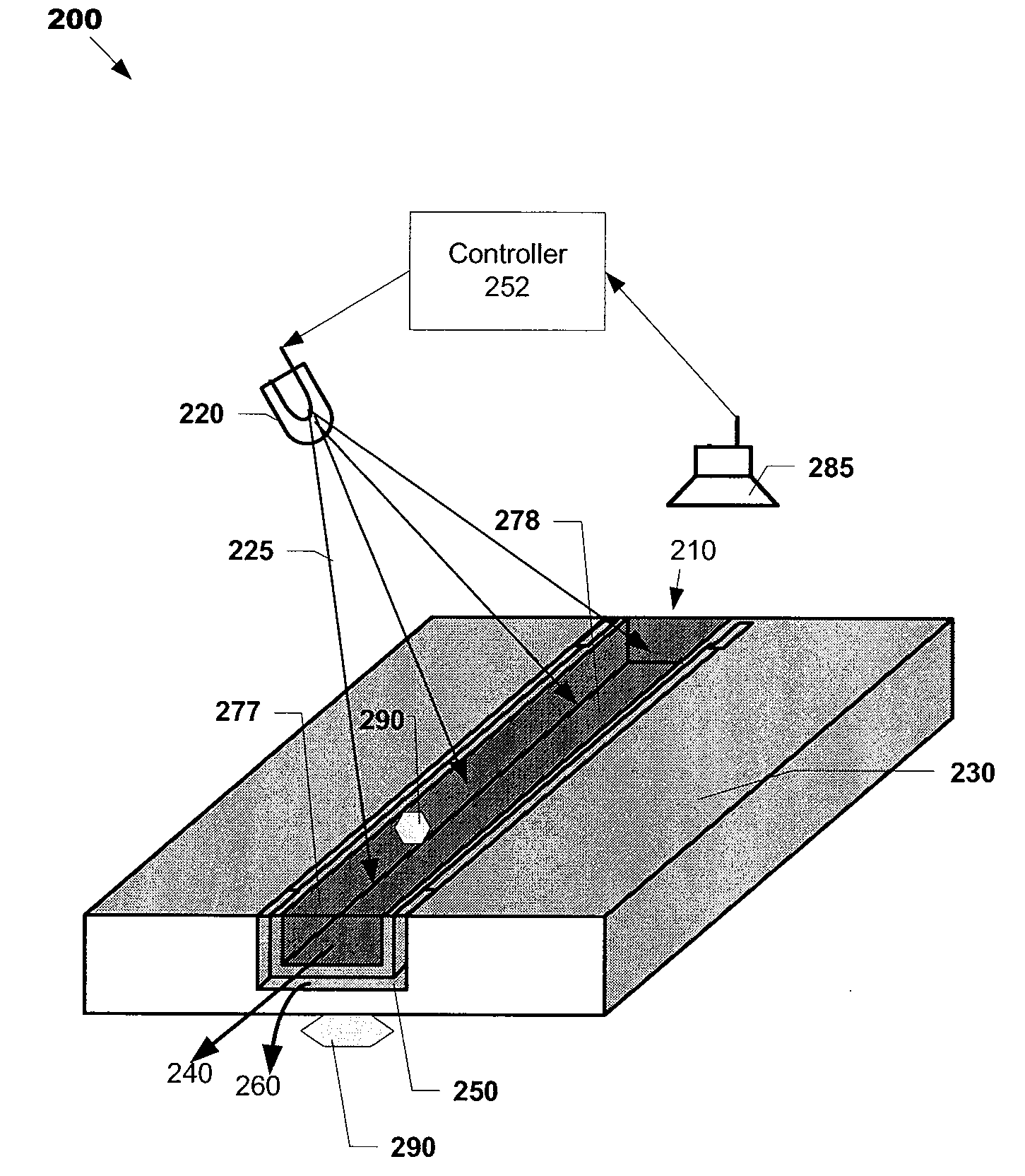
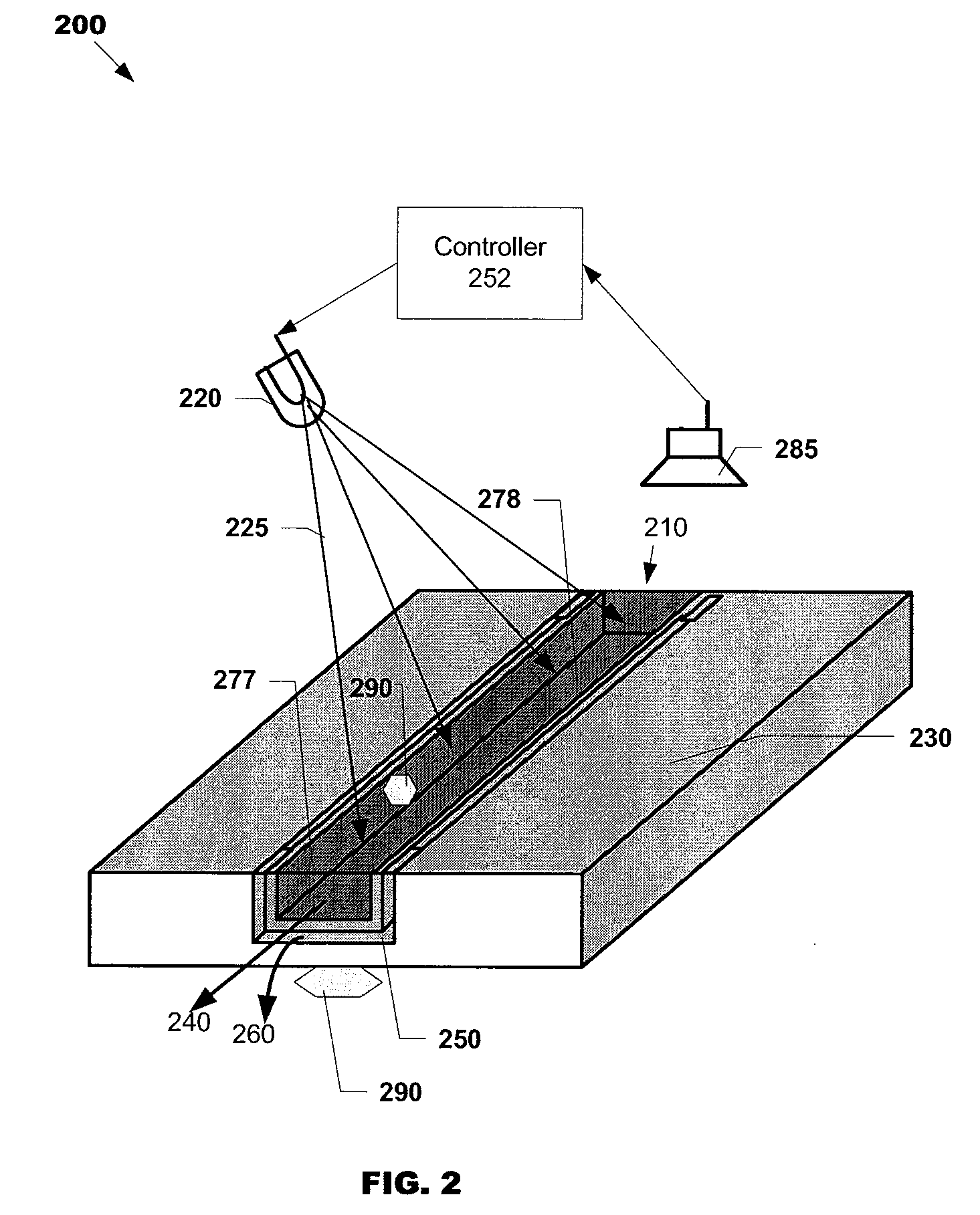
[0052]Referring now to FIG. 6, FIG. 6 illustrates an apparatus 600 in accordance with the second exemplary embodiment. An energy source 620 produces radiation 625a and 625b that illuminates a microfluidic chip 630 on two respective illumination portions of the microfluidic chip 630. The microfluidic chip 630 can include at least two microfluidic channels 610a and 610b, each associated with one of the two illumination portions. The microfluidic chip 630 can also optionally include heat-exchange channels 650a and 650b. In some embodiments, flows 660a and 660b may flow through channels 650a and 650b, respectively. At least a portion of the energy in the incident illumination 625a is absorbed by at least one absorption element 690a (e.g., which, as described above with reference to the first exemplary embodiment, can be a coating that covers at least a portion of a wall of channel 610a) operatively connected to the first microfluidic channel 610a. Similarly at least a portion of the ene...

third exemplary embodiment

[0056]FIG. 7 illustrates an apparatus 700 in accordance with a third exemplary embodiment. Apparatus 700 includes a microfluidic chip 730 including at least one microfluidic channel 710. In the illustrated embodiment, channel 710 is generally in the shape of a sine wave.

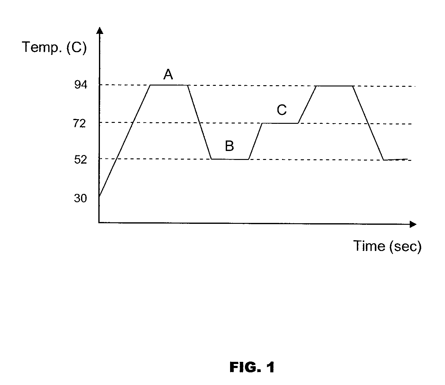
[0057]A temperature controller (e.g., radiation source 720 or other heater, heat-exchange channels 750a,b for containing a heat-exchange fluid 760a,b, and absorptive elements 790a,b) is configured and arranged so as to create three distinct temperature zones (zone 830a, zone 830b, and zone 830c—see FIG. 8).

[0058]Although a particular arrangement of heating / cooling elements are shown, this is only for illustration, as any kind of heaters and heat sinks may be used to create the three unique temperature zones. Accordingly, this embodiment should not be limited to any particular heating or cooling mechanism.

[0059]Preferably, the temperature in each zone is generally held constant and the temperature of any particular zo...


PUM

PropertyMeasurementUnit
wavelengthaaaaaaaaaa

Abstract

At least one exemplary embodiment is directed to an apparatus that includes a microfluidic channel and at least one energy absorbing element, where the energy absorbing element is configured to absorb at least a portion of an incident electromagnetic radiation. The absorption of the radiation by the energy absorbing element varies the temperature of a sample in the microfluidic channel.

Description

[0001]This application claims the benefit of U.S. Provisional Patent Application No. 60 / 806,440, filed on Jun. 30, 2006, which is incorporated herein by this reference.BACKGROUND[0002]1. Field of the Invention[0003]The present invention relates to microfluidic thermal control, and in particular, though not exclusively, to thermal control of microfluidic DNA analysis systems using electrical and / or magnetic (hereafter electromagnetic) radiation as an energy source.[0004]2. Related Art[0005]The detection of nucleic acids is central to medicine, forensic science, industrial processing, crop and animal breeding, and many other fields. The ability to detect disease conditions (e.g., cancer), infectious organisms (e.g., HIV), genetic lineage, genetic markers, and the like, is ubiquitous technology for disease diagnosis and prognosis, marker assisted selection, correct identification of crime scene features, the ability to propagate industrial organisms and many other techniques. Determina...

Claims


Application Information

Patent Timeline
Patent Type & Authority Applications(United States)
IPC IPC(8): C12P19/34C12M1/02F25B29/00F28D15/00F28D7/10F28D21/00F28F23/00F28F7/00
CPCB01L3/5027B01L7/52B01L2200/143B01L2300/1822B01L2400/0487Y10T436/117497G01N35/08C12Q1/686Y10T436/115831C12Q2565/629C12Q2561/113G06T7/11B01L3/50273B01L7/525B01L2300/1827B01L2300/1877B01L3/502715B01L2300/0654B01L2300/0829B01L2300/18B01L2200/10B01L2300/0627B01L2300/1811G01N21/71G06T7/0012G06T2207/10004G06T2207/30072
Inventor ZENG, SHULINHASSON, KENTON C.DALE, GREGORY A.KEADY, JOHN
Owner CANON US LIFE SCIENCES INC
Why Eureka
Try Eureka