Etching method and etching equipment

a technology of etching equipment and etching method, which is applied in the direction of electrical equipment, decorative surface effects, decorative arts, etc., can solve the problems of ion bombardment damage to the tapered portion of the trench, damage to the surface protection of the upper portion of the side walls, so as to achieve rapid increase of reaction rate, high etching rate, and maintain throughput

Active Publication Date: 2008-07-24
HITACHI HIGH-TECH CORP
View PDF18 Cites 3 Cited by
  • Summary
  • Abstract
  • Description
  • Claims
  • Application Information

AI Technical Summary

Benefits of technology

[0013]The object of the present invention is to provide an etching method and an etching apparatus capable of etching a trench without causing any damages, such as recess and surface roughness, on the side wall surface of the trench while maintaining a high-etching rate.
[0015]According to the present invention, a trench profile having no side wall damage can be formed while maintaining a high-etching rate, that is, while maintaining throughput. Furthermore, since the protection of the side walls of the trench is realized by adding gas containing a small amount of H (hydrogen), the rapid increase of reaction byproducts attaching to the inner walls of the chamber can be disregarded, and the inside of the chamber can maintain a clean condition.

Problems solved by technology

However, according to the above-mentioned prior art performing high-rate etching using mainly fluorine-based gases, the effect of protecting the side walls of the trench is insufficient, and especially when forming a deep trench, the protection of the upper portion of the side walls of the etched trench becomes insufficient while the etching is progressed in the depth direction, causing damages such as recess and roughness to be generated on the surface of the side walls.
That is, considering the embedding process that follows the forming of the trench, the trench must be somewhat tapered, and in that case, the tapered portion of the trench is subjected to damage by the ion bombardment if the ionicity is high.
However, there is no consideration on the above problem according to the prior art method disclosed in patent document 1, and since the method carries out etching with high ionicity, the ion bombardment on the inner wall surfaces of the trench may damage the protective layer and generate recesses and surface roughness on the side walls.
Since the etching method for a trench having a high aspect ratio is not established according to patent document 2, the protections on the upper portion of the side walls of the trench having completed etching becomes insufficient, and the side walls are damaged at the end of the etching process.

Method used


Image

  • Etching method and etching equipment
  • Etching method and etching equipment
  • Etching method and etching equipment

Examples


embodiment 1

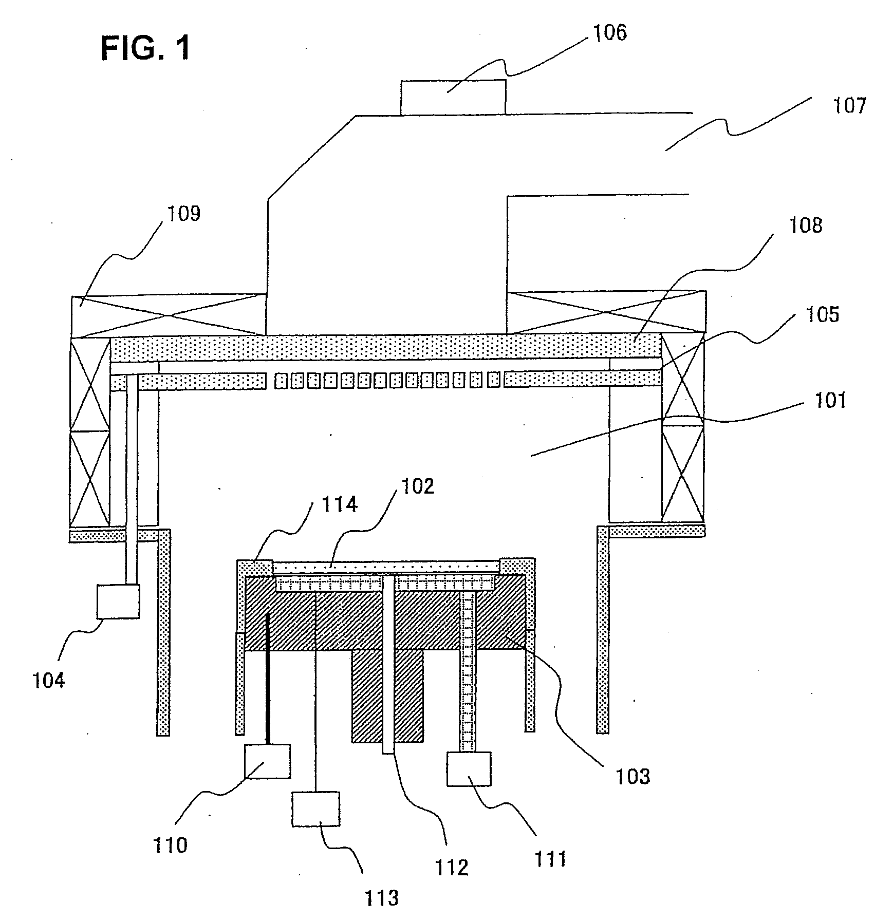
[0021]FIG. 1 shows a microwave plasma etching equipment according to embodiment 1 of the present invention utilizing microwaves and magnetic fields as means for generating plasma.

[0022]In the present equipment, etching gas is supplied to an etching processing chamber 101 from a gas supply means 104 via a permeation window 105 having a porous structure made of quartz, for example.

[0023]Further, microwaves generated from a microwave generator (not shown) are transmitted via a matching box 106 and a waveguide 107 and through a microwave introduction window 108 into the etching processing chamber 101 to turn the above-mentioned etching gas into plasma.

[0024]In order to enhance the radiation efficiency, a solenoid coil 109 for generating magnetic fields is disposed around the etching chamber, a magnetic field of 0.0875 T is generated, and high-density plasma is generated by the magnetic field utilizing electron cyclotron resonance. A sample stage 103 is disposed in the etching chamber 10...


PUM

PropertyMeasurementUnit
temperatureaaaaaaaaaa
flow rateaaaaaaaaaa

Abstract

The invention provides an etching method for realizing trench etching without causing any damages to the side walls of the trench while maintaining a high-etching rate. The plasma etching method relates to forming a groove or a hole by forming a silicon trench to a silicon substrate or a silicon substrate having a silicon oxide dielectric layer via a mixed gas plasma containing a mixed gas of SF6 and O2 or a mixed gas of SF6, O2 and SiF4 and having added thereto a gas containing hydrogen within the range of 5 to 16% (percent concentration) of the total gas flow rate of the mixed gas.

Description

[0001]The present application is based on and claims priority of Japanese patent application No. 2005-295462 filed on Oct. 7, 2005, the entire contents of which are hereby incorporated by reference. This application is a Divisional application of prior application Ser. No. 11 / 288,105, filed Nov. 29, 2005, the contents of which are incorporated herein by reference in their entirety.BACKGROUND OF THE INVENTION[0002]1. Field of the Invention[0003]The present invention relates to a method and equipment for etching a semiconductor device. More specifically, the present invention relates to a method and equipment capable of preventing the side walls of a trench (groove or hole) from being damaged.[0004]2. Description of the Related Art[0005]Recently, silicon (Si) trench etching is applied as a device isolation technique to devices such as in-vehicle pressure-resistant IGBT (insulated gate bipolar transistor) devices corresponding to hybrid vehicles, which is drawing keen attentions in the...

Claims


Application Information

Patent Timeline
Patent Type & Authority Applications(United States)
IPC IPC(8): H01L21/3065
CPCH01L21/76898H01L21/3065
Inventor TAKATA, KAZUOKUDOU, YUTAKATANI, SATOSHI
Owner HITACHI HIGH-TECH CORP
Why Eureka
Try Eureka