Plasma etching method

a technology of etching method and plasma, which is applied in the field of etching method, can solve the problems of negative charge and damage to the etching surface, and achieve the effect of high etching rate and high mask selection ratio

Inactive Publication Date: 2014-05-29
TOKYO ELECTRON LTD
View PDF4 Cites 52 Cited by
  • Summary
  • Abstract
  • Description
  • Claims
  • Application Information

AI Technical Summary

Benefits of technology

[0010]According to the present invention, it is possible to provide a plasma etching method that controls the occurrence of necking and bowing and has a high mask selection ratio at a high etch rate.

Problems solved by technology

Furthermore, shading damage may be caused by the bottom of the hole thus being positively charged.

Method used


Image

  • Plasma etching method
  • Plasma etching method
  • Plasma etching method

Examples


first embodiment

[0077]Next, a description is given of an experiment by which effects of the method of this embodiment were confirmed.

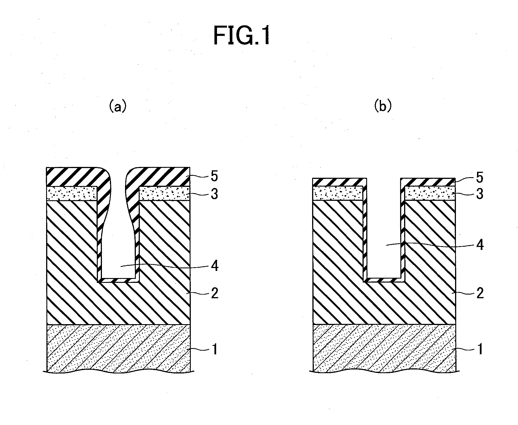
[0078]An object of processing having an oxide film deposited on a silicon substrate, having a nitride film and an oxide film successively stacked thereon as a hard mask, and having Poly-Si further stacked was used. A sample having Poly-Si and the hard mask etched in advance (a punch step) was prepared, and plasma etching was performed under the etching conditions illustrated in detail below.

(First Step (the above-described first etching process))

Etching Gas: C4F6 / Ar / O2=80 / 400 / 60 sccm

Pressure: 20 mTorr

First High-Frequency Power Supply Output: 1700 W

Second High-Frequency Power Supply Output: 6600 W

[0079]High-Frequency Power Supply Pulse Interval: 10 kHz (100 μsec)

Direct-Current Voltage from First Direct-Current Power Supply: 150 V (during PLASMA ON), 500 V (during PLASMA OFF)

Etching Time: 180 sec

[0080](Second Step (the above-described third etching process))

Etching Gas:...

second embodiment

[0086]Plasma etching was performed in the same process as in the first embodiment except that the recipe of Third Step (the above-described second etching process) in the first embodiment was changed. The specific etching conditions are illustrated below.

(First Step (the above-described first etching process))

Etching Gas: C4F6 / Ar / O2=80 / 400 / 60 sccm

Pressure: 20 mTorr

First High-Frequency Power Supply Output: 1700 W

Second High-Frequency Power Supply Output: 6600 W

[0087]High-Frequency Power Supply Pulse Interval: 10 kHz (100 μsec)

Direct-Current Voltage from First Direct-Current Power Supply: 150 V (during PLASMA ON), 500 V (during PLASMA OFF)

Etching Time: 180 sec

[0088](Second Step (the above-described third etching process))

Etching Gas: C4F6 / C4F8 / Ar / O2=40 / 40 / 400 / 50 sccm

Pressure: 20 mTorr

First High-Frequency Power Supply Output: 1700 W

Second High-Frequency Power Supply Output: 6600 W

[0089]High-Frequency Power Supply Pulse Interval: 10 kHz (100 μsec)

Direct-Current Voltage from First Direct...

third embodiment

[0093]In this embodiment, as described above, first, the mask selection ratio is increased using highly adhesive radicals as the first etching process of the plasma etching method. Then, as the second etching process, necking is suppressed using radicals less adhesive than in the first etching process. At this time, a period of PLASMA ON and a period of PLASMA OFF are alternately formed in a pulsed manner, and a negative direct-current voltage is applied in synchronization with the on / off of a plasma so that the absolute value of the applied voltage is greater in the period of PLASMA OFF than in the period of PLASMA ON, so as to effectively prevent reduction in the mask remaining film.

[0094]A description is given, using Table 1 of FIG. 9, of an experiment by which the effect of a high flow rate of argon gas and a short pulse interval of a high-frequency power supply was confirmed in the second etching process at this time.

[0095]Table 1 illustrates a mask selection ratio under each e...


PUM

PropertyMeasurementUnit
aspect ratioaaaaaaaaaa
frequencyaaaaaaaaaa

Abstract

A plasma etching method using a plasma etching apparatus including a lower electrode and an upper electrode is provided. The plasma etching method includes a first etching step of performing plasma etching using a first process gas and a second etching step of performing the plasma etching using a second process gas. The adhesion of a radical of the second process gas to an object of processing is less than the adhesion of a radical of the first process gas to the object of processing. While alternately repeating a first condition of turning on high-frequency electric power for plasma generation and a second condition of turning off the high-frequency electric power, the second etching step applies a negative direct-current voltage to the upper electrode so that the absolute value of the applied voltage is greater in a period of the second condition than in a period of the first condition.

Description

TECHNICAL FIELD[0001]The present invention relates to plasma etching methods that perform plasma etching on substrates using a plasma.BACKGROUND ART[0002]For example, in semiconductor device manufacturing processes, a plasma etching process, which performs etching with a plasma using a resist as a mask, is frequently employed in order to form a predetermined pattern on a predetermined layer formed on a semiconductor wafer, which is an object of processing.[0003]HARC (High Aspect Ratio Contact) etching of an aspect ratio of 20 or more has been demanded by recent progress in the microfabrication of semiconductor devices. Recently, high aspect ratio etching of an aspect ratio higher than 40 has been demanded as the next generation HARC.[0004]In such HARC etching, an etching mask such as a photoresist is negatively charged, and electric charge is neutralized on the etched surface in the beginning of etching. When the aspect ratio becomes higher with the progress of etching, positive ion...

Claims


Application Information

Patent Timeline
Patent Type & Authority Applications(United States)
IPC IPC(8): H05H1/46
CPCH01L21/31116H01L21/31144H01J37/32091H01J37/32165H01J2237/334H01L21/67069H01L21/02164H01L21/32137H01L21/3065H05H1/46
Inventor NAKAGAWA, AKIRAYAMAZAKI, FUMIOMOCHIZUKI, HIROMI
Owner TOKYO ELECTRON LTD
Why Eureka
Try Eureka