[0012]The present invention provides for improvements in splints used for transporting injured patients from a field location to a treatment facility. Such improvements include: (1) splints with radiolucent properties around and along the region of the injury, thus allowing X-
ray, Cat Scan and
MRI imaging of the injury without the need for removing the splint; (2) a portable splint kit which may be packaged, transported, disassembled, or reassembled in the field, quickly and efficiently; (3) splint assemblies which provide both a splinting function and apply a quantifiable traction force to one or two broken femurs; and, (4) a splint modeling
system having adjustment and fixation features allowing the splinting of any limb, joint or body part on any human of any size or age.
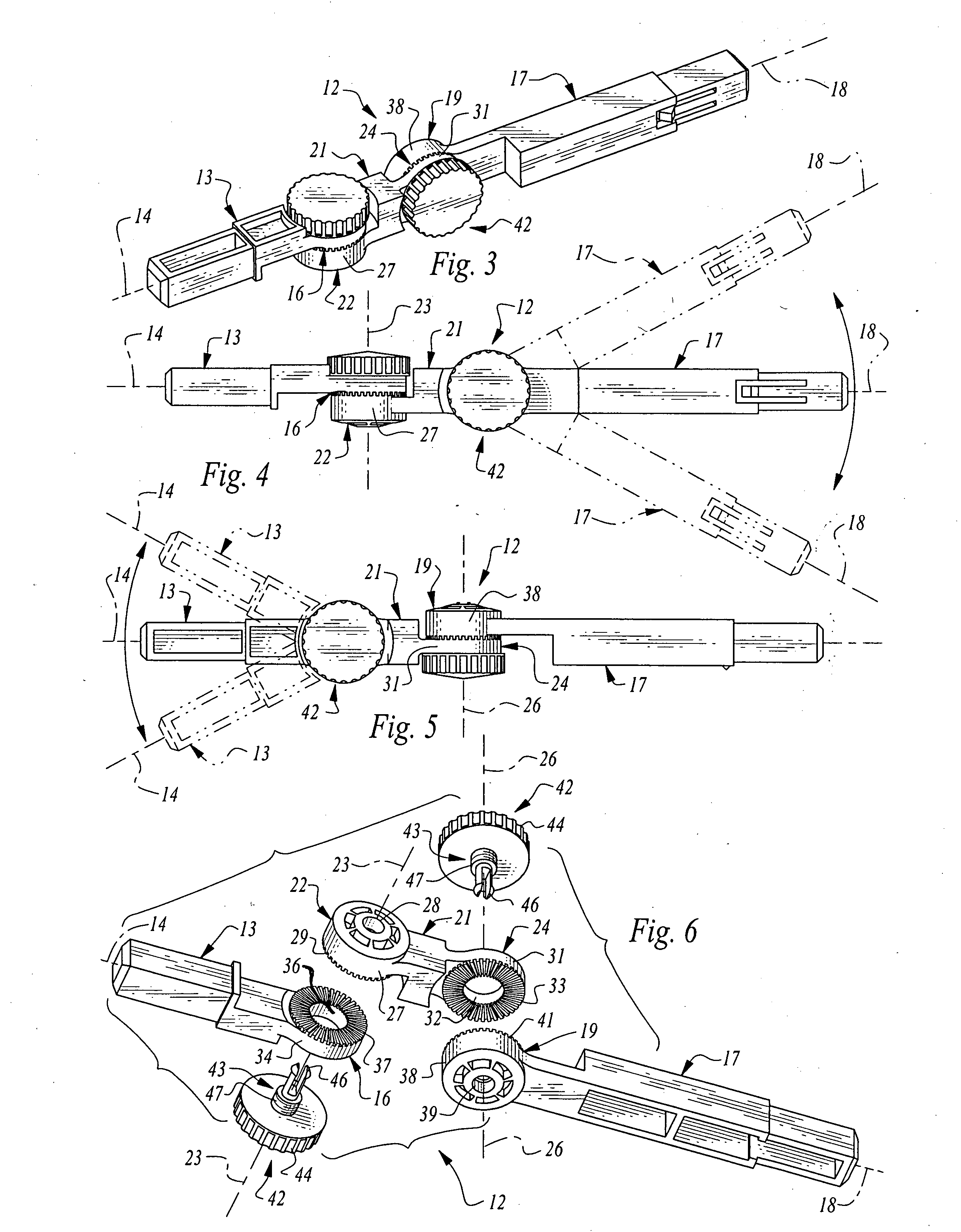
[0013]The heart of the splint modeling
system is an articulated, adjustable, and lockable, alignment arm. The alignment arm is comprised of two arm segments, each having one respective end pivotally attached to a respective end of an intermediate connector body. The axes for the pivotal attachments are perpendicular with respect to each other. The arm segments may be independently adjusted and selectively locked into a plurality of rotational positions about a respective axis. In use, the alignment arm is shaped adjacent and parallel to any
fractured bone or joint, thereby producing a modeled structure having the same configuration and orientation as the injured limb. The procedure affords accurate splinting of the fractured member without movement or production of pain. Rotating locking knobs on the connector body ensures that the alignment arm retains the shape of the injury. Once the alignment arm is locked into the desired configuration, the arm segments are lengthened through the use of arm extenders fitted with padded material. End pads may also be installed into the free ends of the arm extenders. The
assembly is then gently placed on the limb or body, and secured in position with two or more fabric cravats of variable lengths and widths. This affords safe movement of the patient, while securing the injured limbs and joints of the patient in the same position they were found by medical personnel.
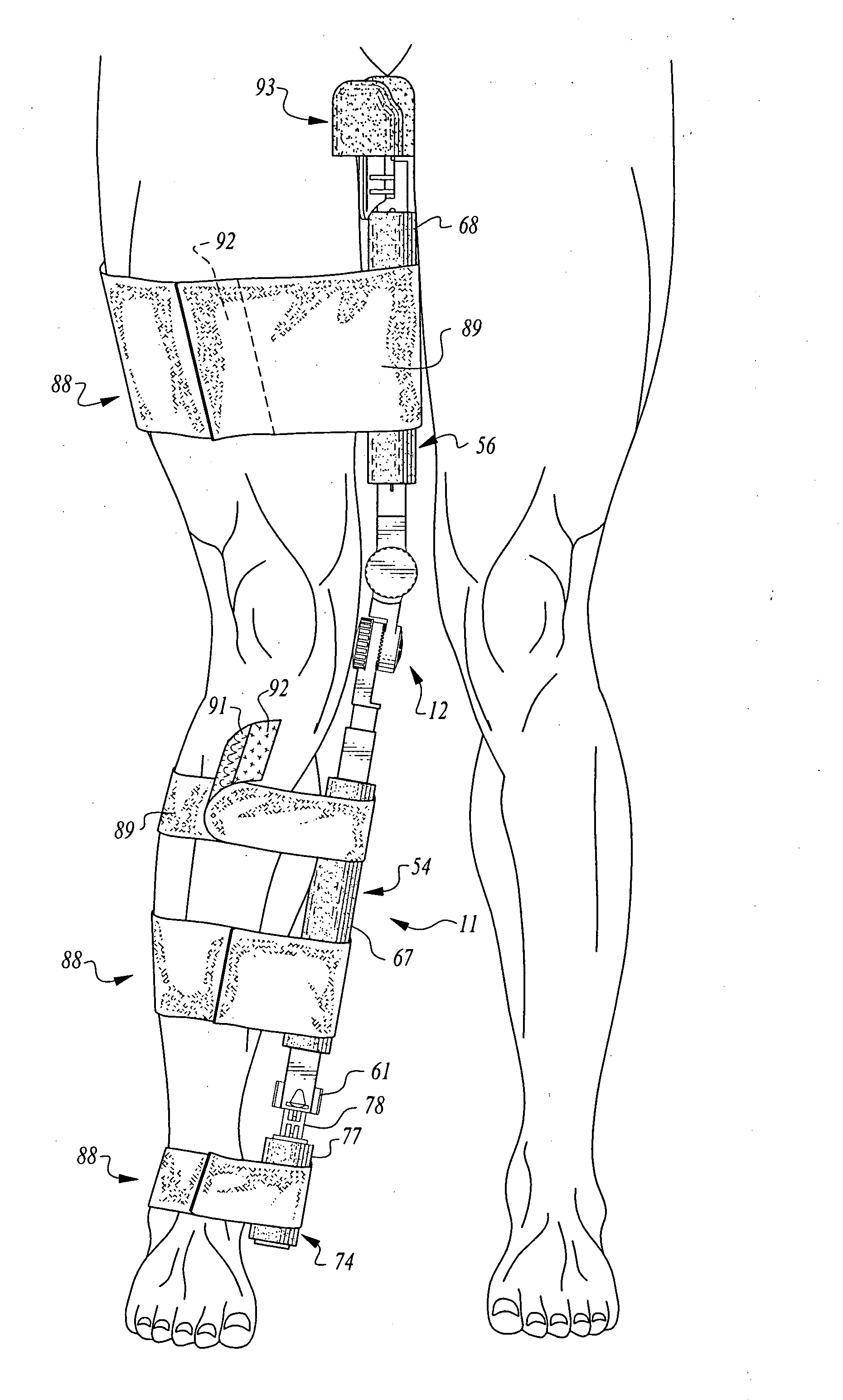
[0015]Another application for certain components of the invention is to splint, for example, leg injuries also needing a pre-determined amount of traction. In this application, a bilateral traction splint
assembly is provided, including a spring
pulley and cable structure, entirely mounted and enclosed within in a telescopic housing at the distal end of the
assembly. The same arm extenders used in the articulated splint are coupled together to form a straight splint shaft, extending between a base
cushion seated against the user's
ischial tuberosity at the
proximate end of the assembly, and an
ankle cravat secured to the user's
ankle at the distal end of the assembly. The splint shaft is padded on both lateral surfaces
lying along the inner sides the user's leg, providing enhanced
patient comfort.
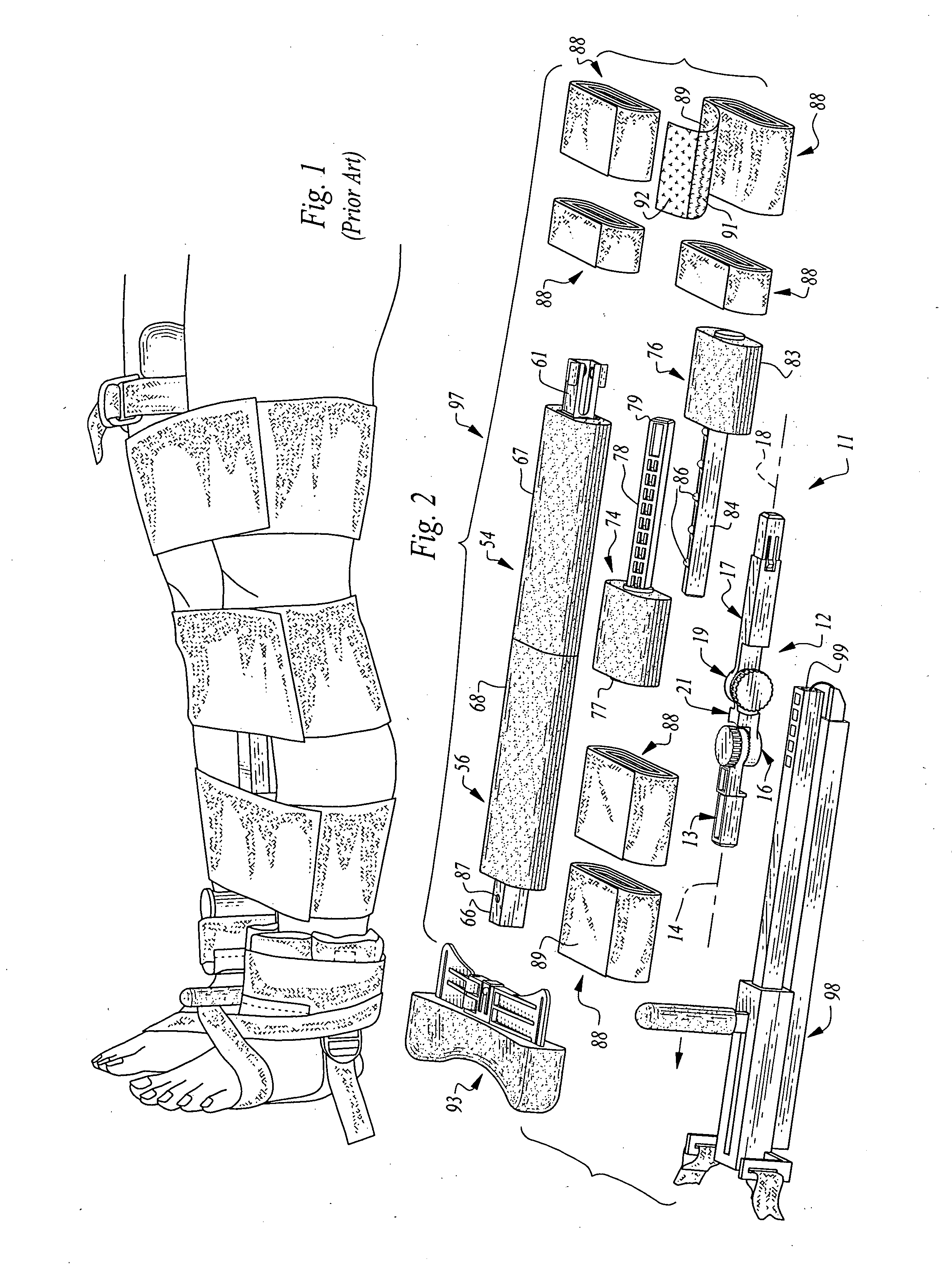
[0016]A carrying case is also provided, housing a kit comprising a disassembled bilateral traction splint, an articulated alignment arm, padded arm extenders, end pads, and a plurality of fabric cravats of varying widths and lengths. In the hands of properly trained medical personnel, this kit is capable of quickly and correctly providing a traction splint, if needed, for fractured femurs, or providing a modeled splint for stabilizing a limb extending from the body of any sized adult or child.

