
Performance Degradation Root Cause Prediction in a Distributed Computing System

a distributed computing and root cause prediction technology, applied in computing, instruments, electric digital data processing, etc., can solve the problems of slos, affecting the efficiency of distributed information technology environment management, and affecting the stability of the system, so as to avoid inaccuracy in capacity planning, reduce computational complexity, and improve efficiency and effectiveness

Inactive Publication Date: 2008-07-24
IBM CORP
View PDF3 Cites 11 Cited by
  • Summary
  • Abstract
  • Description
  • Claims
  • Application Information

AI Technical Summary

Benefits of technology

The present invention provides techniques for efficient and effective root cause prediction of performance degradation and failure in a distributed computing system. These techniques offer several advantages over conventional methodologies, including reducing the number of components to be investigated, avoiding inaccuracy in capacity planning and arrival traffic throttling estimations, and circumventing problems faced by standard network prediction approaches. The method and apparatus of the invention are low computational complexity and well-suited for online implementation. Overall, the invention helps system administrators quickly locate a potential performance degradation root cause, preventing major service degradation for users.

Problems solved by technology

One of the major challenges for administrators of distributed information technology environments is maintenance of service level objectives, or SLOs.
These methods, however, do not take into account system failures which can result in unexpected performance values and thus jeopardize capacity planning estimations and the limits imposed on the arriving traffic.
Existing methods for network failure prediction are typically based on either transmission control protocol (TCP) related data or management information base (MIB) variables, both of which present highly non-stationary characteristics making it difficult to accurately model the dynamics of the system without large amounts of information and processing.

Method used


Image

  • Performance Degradation Root Cause Prediction in a Distributed Computing System
  • Performance Degradation Root Cause Prediction in a Distributed Computing System
  • Performance Degradation Root Cause Prediction in a Distributed Computing System

Examples


Embodiment Construction

[0015]The present invention will be described in the context of illustrative embodiments of an exemplary data processing system architecture. It should be understood, however, that the invention is not limited to use with any particular system architecture. Rather, the invention is more generally applicable to any distributed computing system in which it is desirable to perform efficient and effective performance degradation root cause prediction.

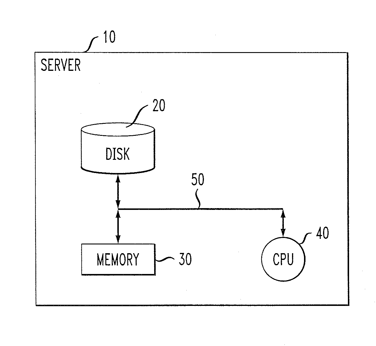
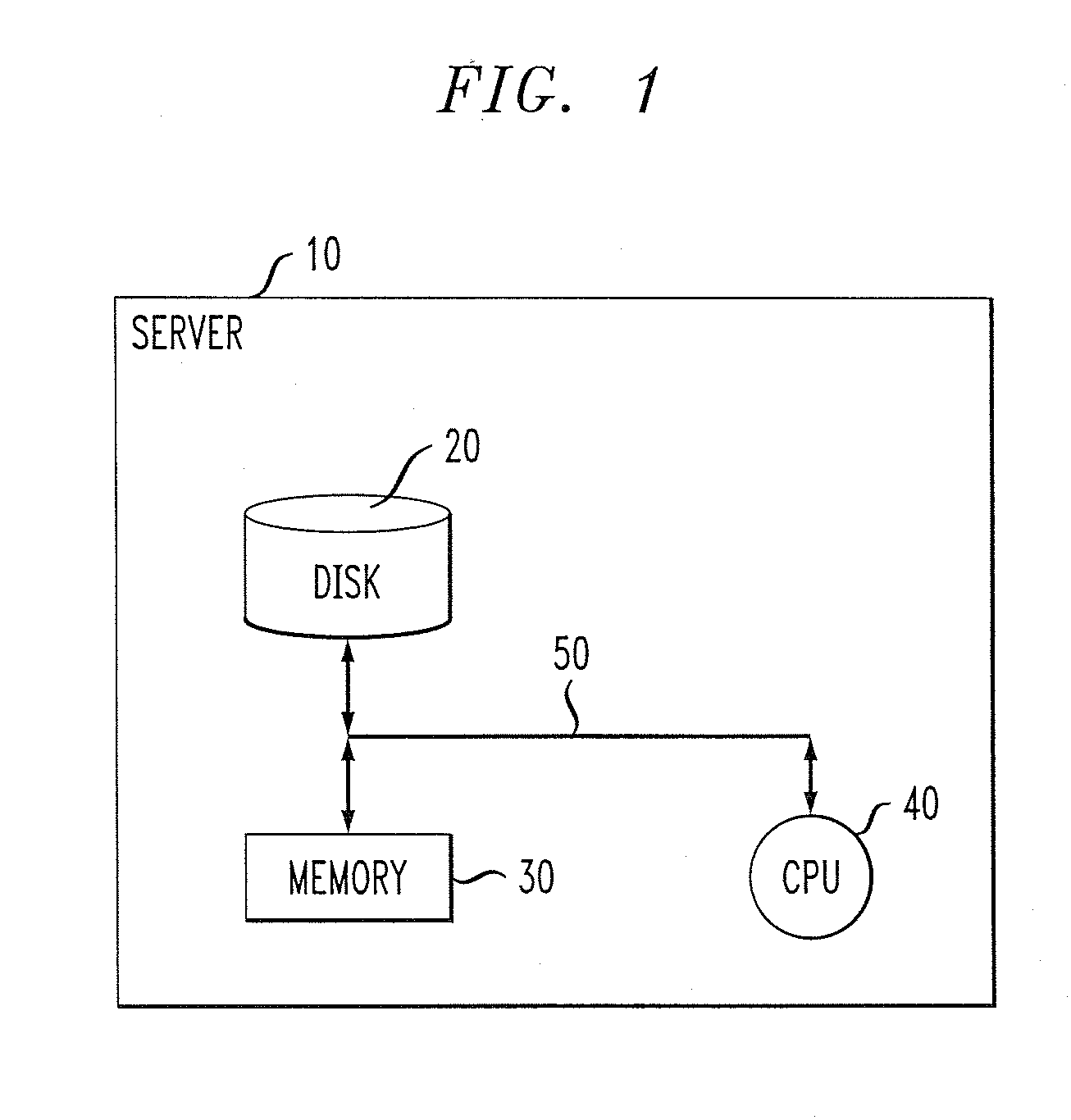
[0016]FIG. 1 is a block diagram depicting an exemplary hardware implementation suitable for employing one or more proactive performance degradation root cause prediction methodologies, according to an embodiment of the present invention. As shown in the figure, a server 10 preferably includes a disk 20, or alternative data storage means, memory 30 and a central processing unit (CPU) 40, or an alternative processor, operatively coupled together via a bus 50 or other connection arrangement.

[0017]It is to be appreciated that the term “processo...


PUM


Abstract

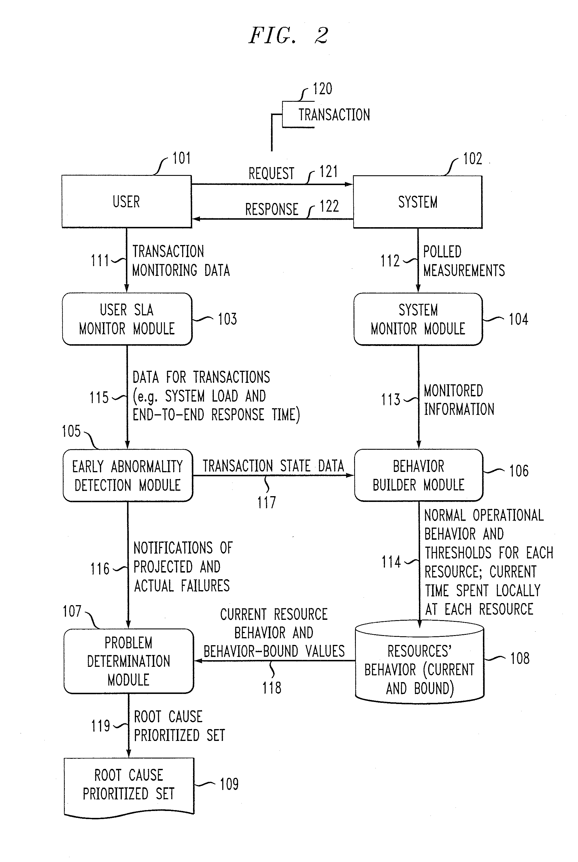
A method of identifying at least one resource in a distributed computing system which is a potential root cause of performance degradation of the system includes the steps of: computing operational bounds for the system and operational bounds for at least one resource in the system; comparing current end-to-end system performance with the operational bounds for the system; when the current end-to-end system performance is outside of the operational bounds for the system, comparing current performance of the at least one resource in the system with the operational bounds for the at least one resource; and generating at least one output identifying the at least one resource in the system which is a potential root cause of performance degradation of the system.

Description

CROSS-REFERENCE TO RELATED APPLICATION(S)[0001]This application is a continuation of pending U.S. application Ser. No. 11 / 435,411 filed on May 17, 2006, the disclosure of which is incorporated herein by reference.FIELD OF THE INVENTION[0002]The present invention relates generally to distributed information technology, and more particularly relates to performance degradation root cause prediction in a distributed computing environment.BACKGROUND OF THE INVENTION[0003]One of the major challenges for administrators of distributed information technology environments is maintenance of service level objectives, or SLOs. In accomplishing this goal, it is important that the administrator pinpoint the potential root cause of a system fault as soon as user transaction performance begins to degrade so that corrective action can be taken before an SLO violation occurs, such as the user perceiving major service degradation and / or disruption.[0004]Existing methods for application-level root cause...

Claims


Application Information

Patent Timeline
Patent Type & Authority Applications(United States)
IPC IPC(8): G06F17/30
CPCG06F11/008
Inventor AGARWAL, MANOJ K.KAR, GAUTAMNEOGI, ANINDYASAILER, ANCA
Owner IBM CORP
Learn More