
Suppressing register renaming for conditional instructions predicted as not executed

a technology of conditional instructions and register renaming, applied in the field of data processing systems, can solve problems such as increasing the circuit area and power consumption of the system concerned, and stalling processing

Active Publication Date: 2008-07-24
ARM LTD
View PDF3 Cites 24 Cited by
  • Summary
  • Abstract
  • Description
  • Claims
  • Application Information

AI Technical Summary

Benefits of technology

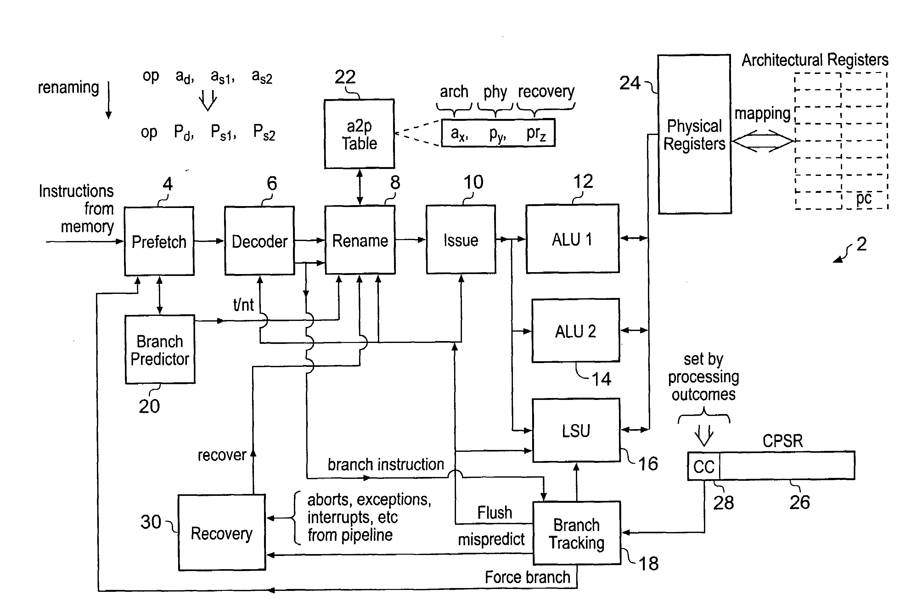
[0016]The present technique recognises that prediction mechanisms may be used to generate a prediction as to whether or not a particular conditional instruction will or will not be executed and then register renaming for a conditional instruction predicted to be not executed can be suppressed thereby preserving physical register resources such these are available for use in connection with the processing of other program instructions. If the prediction is accurate, then the conditional instruction will not be executed and the fact that it was not subject to renaming will have no impact. If the prediction turns out to be incorrect, then a recovery mechanism can be used to recover the situation such that inappropriate changes to architectural state are reversed and the conditional instruction concerned forced to be subject to renaming and then reissued for execution. When the prediction accuracy is high and the cost in terms of physical register usage by renaming a conditional instruction which will not be executed is high, then the present technique is justified and provides an advantageous balance between overhead and performance.
[0018]In connection with such conditional branch instructions it will be appreciated that it is known within systems to already provide branch prediction mechanisms so as to predict program flow and keep the instruction pipeline full with the correct sequence of instructions. In order to achieve this, various sophisticated branch prediction mechanisms are already provided, typically in association with a pre-fetch unit, and these branch prediction mechanisms can be highly accurate. In this context, the present technique is able to reuse the branch prediction mechanisms which are already provided and exploit the predictions which they make for the additional purpose of suppressing register renaming associated with conditional branch instructions which are predicted as not executed.
[0023]In this context, the prediction resolving circuitry may be responsive to the one or more condition codes set by the one or more processing outcomes of one or more preceding instructions to determine if the prediction which was previously made is or is not correct. This allows the prediction to be resolved in an advantageously straightforward manner.

Problems solved by technology

As an example, if an instruction requires renaming but all of the physical registers provided already be in use for other mappings, then the instruction concerned cannot be subject to register renaming and the processing will stall until physical registers become available.
However, this solution disadvantageously increases the circuit area and power consumption of the system concerned.

Method used


Image

  • Suppressing register renaming for conditional instructions predicted as not executed
  • Suppressing register renaming for conditional instructions predicted as not executed
  • Suppressing register renaming for conditional instructions predicted as not executed

Examples


Embodiment Construction

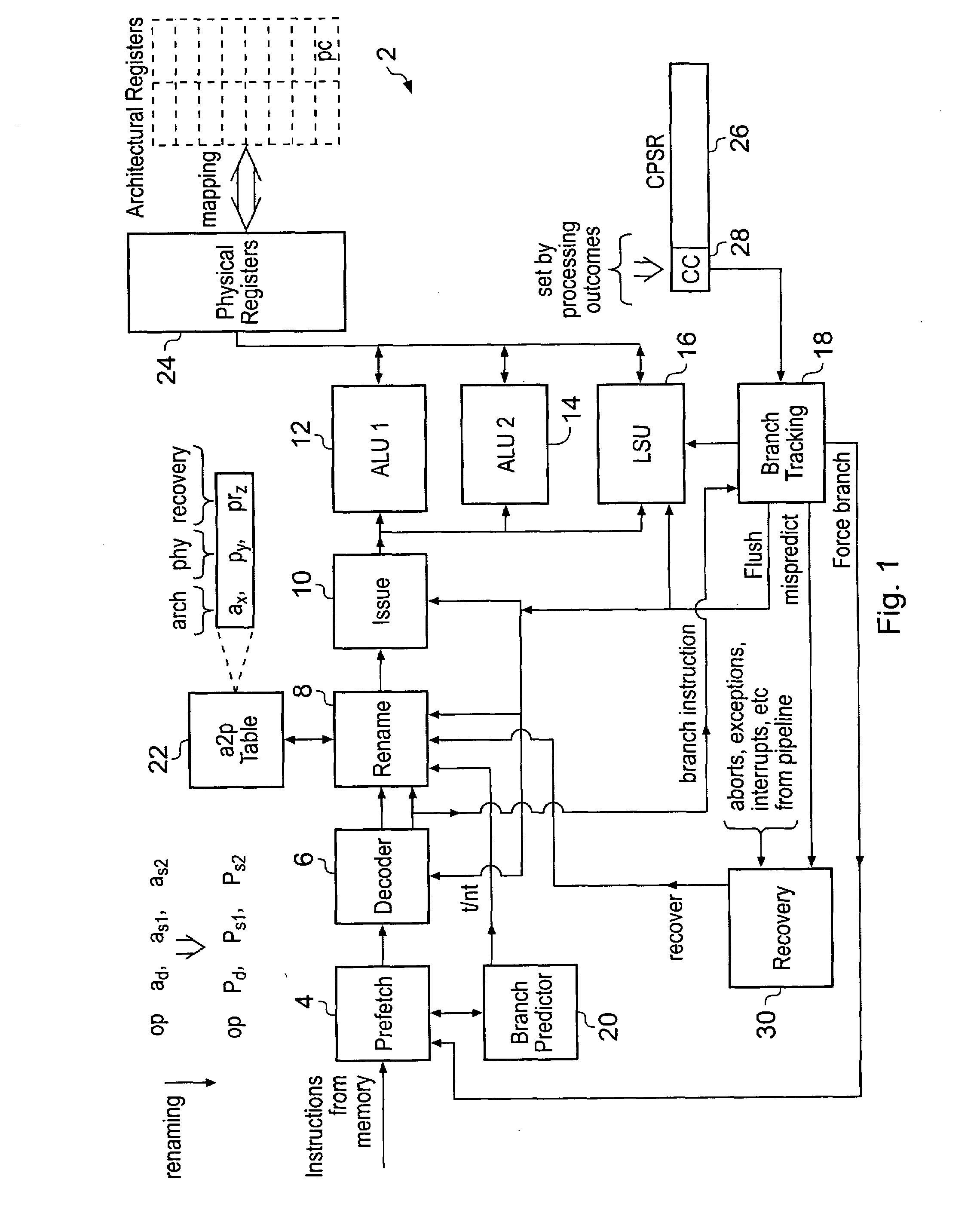
[0047]FIG. 1 schematically illustrates a data processing apparatus 2, which will typically be formed as an integrated circuit containing a processor executing program instructions taken from an instruction set. The instruction set could take a variety of different forms, but may be the ARM instruction set of the type executed by processors provided by ARM Limited of Cambridge England. It will be appreciated that the data processing apparatus 2 will typically include many further elements beyond those illustrated in FIG. 1 but these have been omitted from FIG. 1 for the sake of simplicity.

[0048]FIG. 1 generally illustrates the instruction pipelines provided within the data processing system 2. In particular, the data processing system 2 includes a prefetch unit 4, a decoder 6, a renaming unit 8 and an issue unit 10. These are followed by two data processing units 12, 14, a load store unit 16 and a branch tracking unit 18. In operation program instructions from a memory (not illustrat...


PUM


Abstract

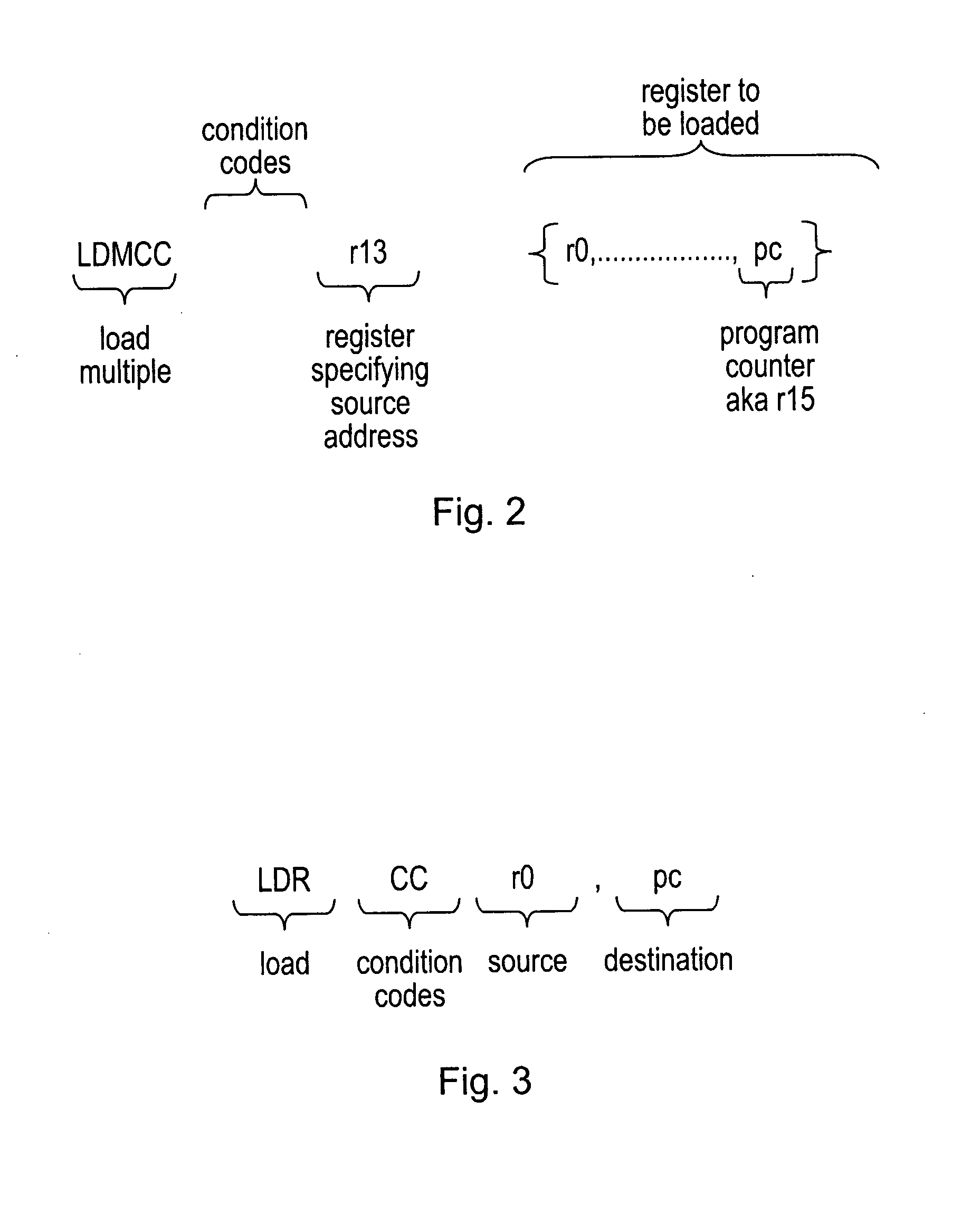
Within a data processing system 2 including a register renaming mechanism 8, 22, register renaming for some conditional instructions which are predicted as not-executed is suppressed. The conditional instructions which are subject to such suppression of renaming may not be all conditional instructions, but may be those which are known to consume a particularly large number of physical registers 24 if they are subject to renaming A conditional load multiple instruction in which multiple registers are loaded with new data values taken from memory in response to signal instruction is an example where the present technique may be used, particularly when one of the registers loaded is the program counter and accordingly the instruction is a conditional branch.

Description

BACKGROUND OF THE INVENTION[0001]1. Field of the Invention[0002]This invention relates to the field of data processing systems. More particularly, this relates to data processing systems using register renaming.[0003]2. Description of the Prior Art[0004]It is known to provide data processing systems utilising the technique of register renaming. In such systems there exists a pool of physical registers which can be mapped to architectural registers as specified within instructions of the instruction set of the data processing system concerned. One example use of such register renaming techniques is to facilitate out-of-order processing. In this context, register renaming allows the system to cope with write-after-write hazards and write-after-read hazards and provide a mechanism for recovering architectural state should processing not proceed as predicted, e.g. as a consequence of a mis-predicted branch instruction, as a consequence of an abort or some other exception.[0005]It will b...

Claims


Application Information

Patent Timeline
Patent Type & Authority Applications(United States)
IPC IPC(8): G06F9/00
CPCG06F9/30043G06F9/384G06F9/30072
Inventor LATAILLE, NORBERT BERNARD EUGENEBEGON, FLORENTAIRAUD, CEDRIC DENIS ROBERTVINCENT, MELANIE
Owner ARM LTD
Learn More