Power control apparatus and method thereof

a power control and power technology, applied in the field of power control apparatus, can solve the problems of increasing the cost of power management units, increasing the amount of leakage current, and increasing the complexity of the design of the power management units b>5/b>

Inactive Publication Date: 2008-07-24
SAMSUNG ELECTRONICS CO LTD
View PDF4 Cites 50 Cited by
  • Summary
  • Abstract
  • Description
  • Claims
  • Application Information

AI Technical Summary

Benefits of technology

[0017]When the power management unit having the state machine enters a power-off state the state machine may output a power-off signal to the state machine in a higher power management unit of the power management unit having the state machine.
[0018]The state machine may receives the response signal and may output a first controller control signal to the MTCMOS controller to control the power of each of the at least one power domain block based on the received response signal.
[0019]The state machine may further output a second controller control signal to the MTCMOS controller to wake up the lower power management unit and the MTCMOS controller may output a second control signal to wake-up the lower power management unit in response to the second controller control signal.
[0020]An exemplary embodiment may further be comprised of a portable terminal comprised of a power control apparatus and a CPU receiving power controlled by the power control apparatus. The portable terminal may be a PDA, cellular phone, media player, wireless computer peripheral, or wireless remote control.
[0021]An exemplary embodiment may further comprise a method of controlling a po

Problems solved by technology

Minimal power consumption has become more an issue as electronic devices are smaller and more highly integrated.
However, since the conventional power management unit 5 needs to control the power of the power domain blocks 6-8,

Method used


Image

  • Power control apparatus and method thereof
  • Power control apparatus and method thereof
  • Power control apparatus and method thereof

Examples


Embodiment Construction

[0027]Hereinafter, exemplary embodiments of the present disclosure will be described in detail with reference to the attached drawings. In the drawings, like numbers refer to like elements throughout.

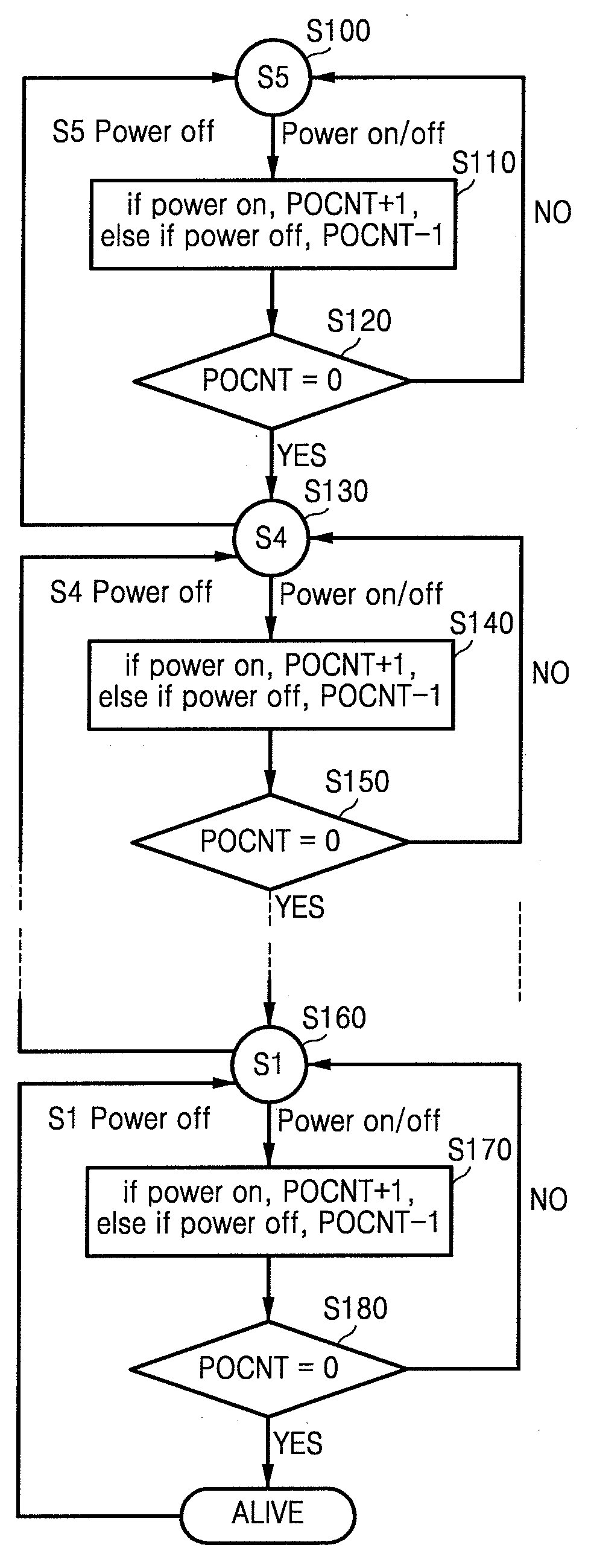
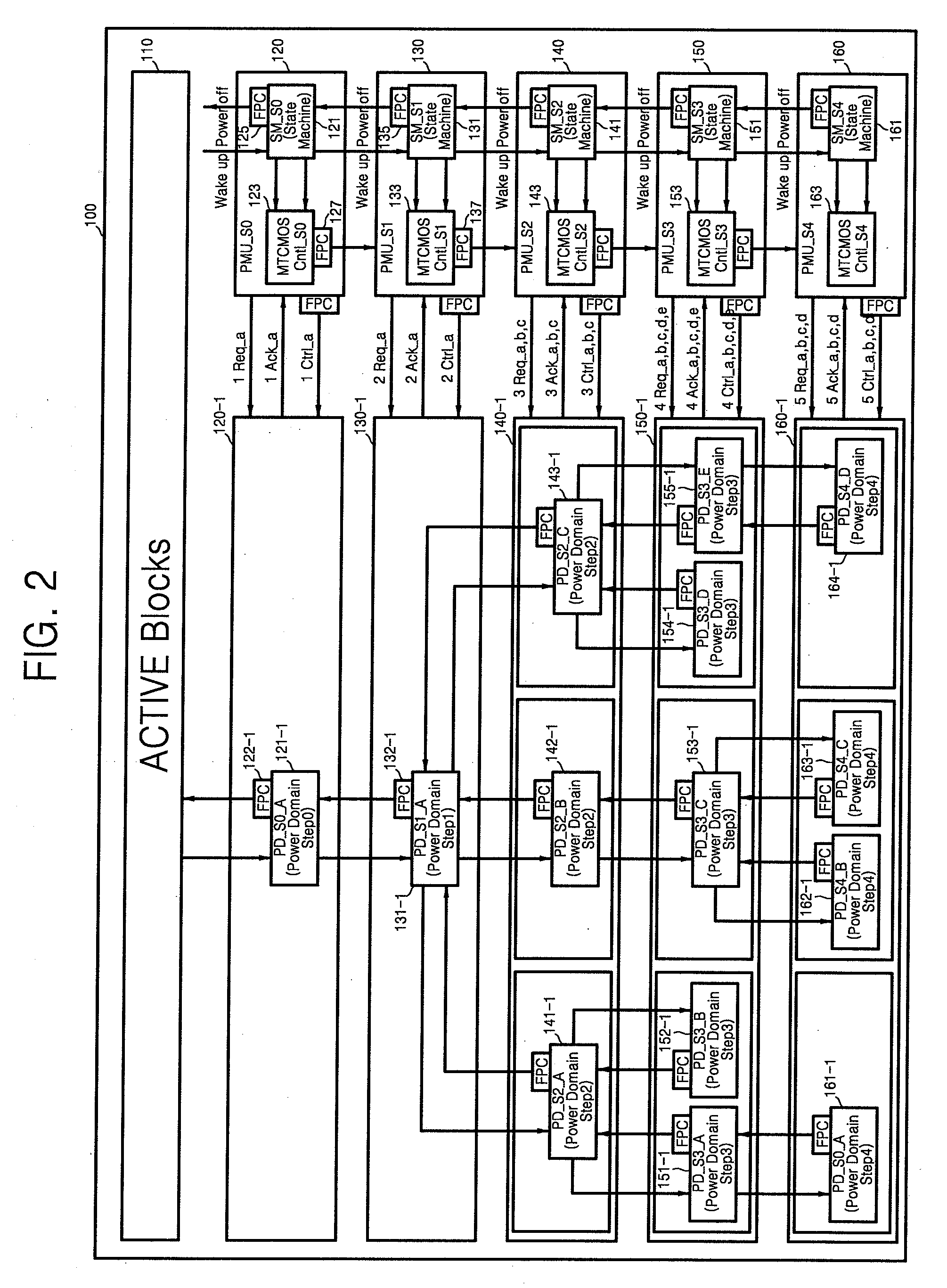
[0028]FIG. 2 is a functional block diagram of a power control apparatus according to an exemplary embodiment of the present disclosure. Referring to FIG. 2, a power control apparatus 100 according to the exemplary embodiment may be realized to include an active block 110 having power that is always maintained in an on state and N number of power management units 120, 130, 140, 150, and 160 having a hierarchical structure, where N is a natural number greater than or equal to 1. Although FIG, 2 illustrates an example in which N is 5, the present invention is not limited thereto.

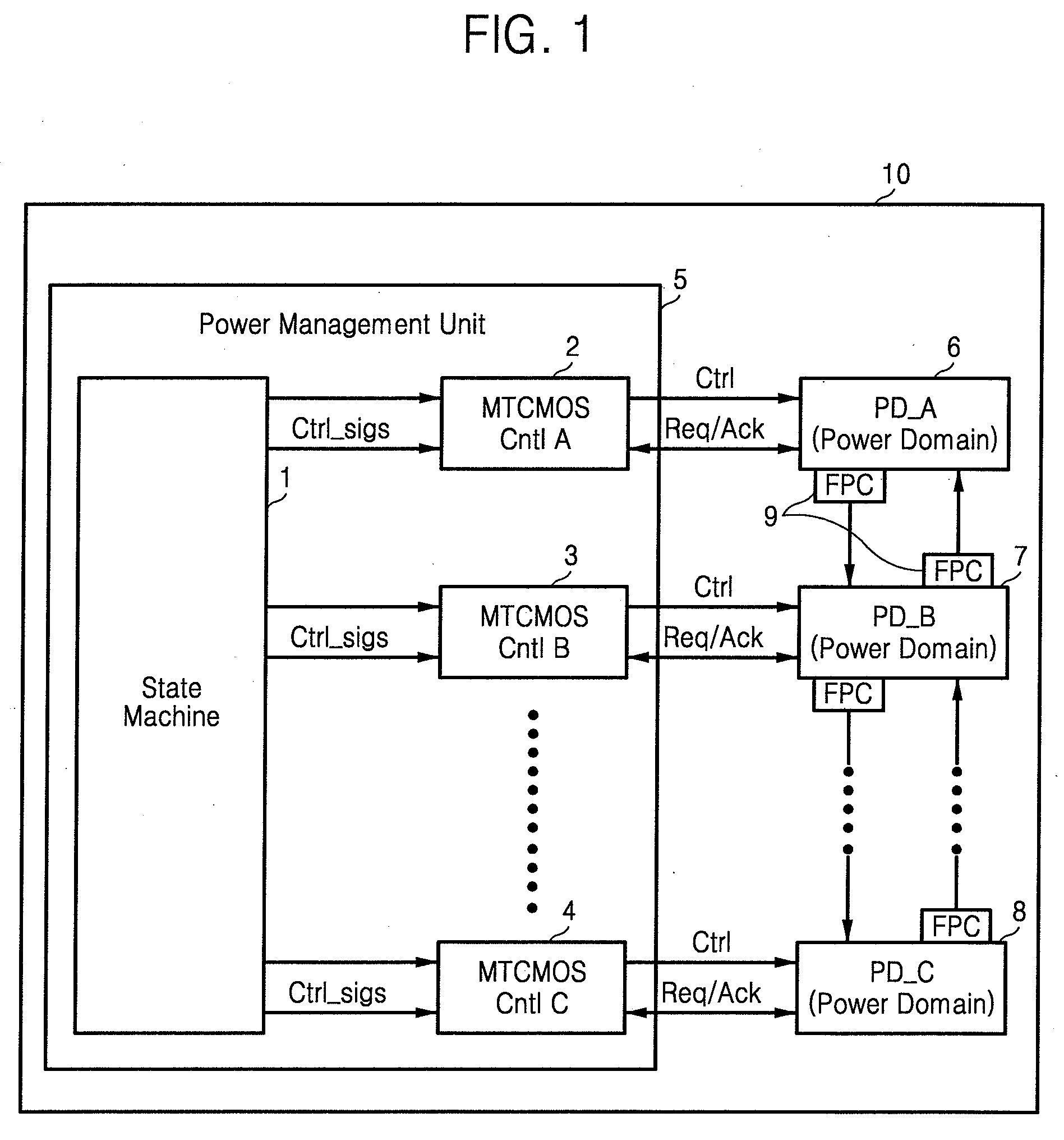
[0029]The power control apparatus 100 is suitable for use in portable terminals, such as mobile phones, PDAs, media players, wireless computer peripheral, or wireless remote control (not shown). The active block 11...


PUM


Abstract

A power control apparatus including an active block in which power is always maintained in an on state and an N number of power management units having a hierarchical structure where N is a natural number greater than or equal to 1. Each of the power management units controls power of at least one power domain block Power of a first power management unit of the N number of the power management units is controlled by the active block, and power of an Nth power management unit of the N number of the power management units is controlled by an (N-1)th power management unit.

Description

CROSS-REFERENCE TO RELATED PATENT APPLICATIONS[0001]This application claims priority under 35 U.S.C. §119 from Korean Patent Application No. 2007-0006903 filed on Jan. 23, 2007, the disclosure of which is incorporated by reference herein,BACKGROUND OF THE INVENTION[0002]1. Field of the Invention[0003]The present disclosure relates to a power control apparatus, and more particularly, to a power control apparatus having top-own type hierarchical power control units, and a control method thereof.[0004]2. Discussion of the Related Art[0005]Minimal power consumption has become more an issue as electronic devices are smaller and more highly integrated. In particular, in the field of mobile communications system on chip (SOC), the reduction in the threshold voltage of a transistor through a refined process helps in the reduction of dynamic power. A method of maintaining minimum necessary information using multi threshold CMOS (MTCMOS) has been proposed in which, in the idle state, power is...

Claims


Application Information

Patent Timeline
IPC IPC(8): G06F1/00
CPCG06F1/3203Y02B60/1278G06F1/3287Y02B60/32Y02B60/1282Y02D10/00Y02D30/50G05F1/10
Inventor KIM, DONG-HAN
Owner SAMSUNG ELECTRONICS CO LTD
Why Eureka
Try Eureka