System and Method for Monitoring Reductant Quality

Active Publication Date: 2008-07-31
FORD GLOBAL TECH LLC
View PDF6 Cites 69 Cited by
  • Summary
  • Abstract
  • Description
  • Claims
  • Application Information

AI Technical Summary

Benefits of technology

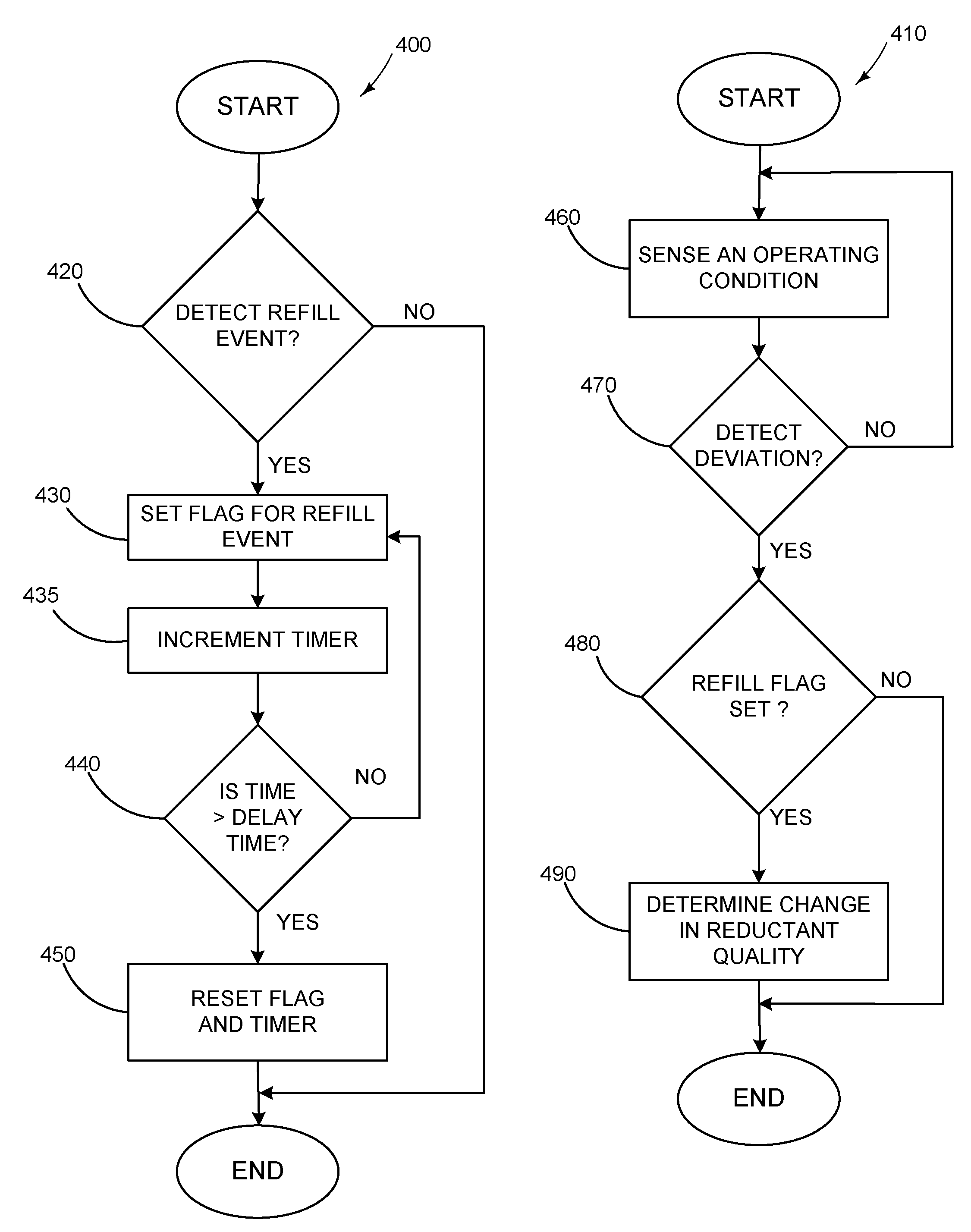
[0004]The inventors herein have realized that a logic driven method may be implemented using existing system infrastructure to monitor reductant quality of an emission control system by determining a pre-refill operating condition of the emission control system, detecting a refill event of a reductant storage device, after said refill event, determining a post-refill operating condition of the emission control system, comparing said post-refill operating condition to said pre-refill operating condition of the emission control system, and detecting a red

Problems solved by technology

However, SCR systems may use a reductant, such as urea, stored in an on-board storage device that may be subject to tampering.
For example, a vehicle operator may introduce an ineffective fluid to a redu

Method used


Image

  • System and Method for Monitoring Reductant Quality
  • System and Method for Monitoring Reductant Quality
  • System and Method for Monitoring Reductant Quality

Examples


Embodiment Construction

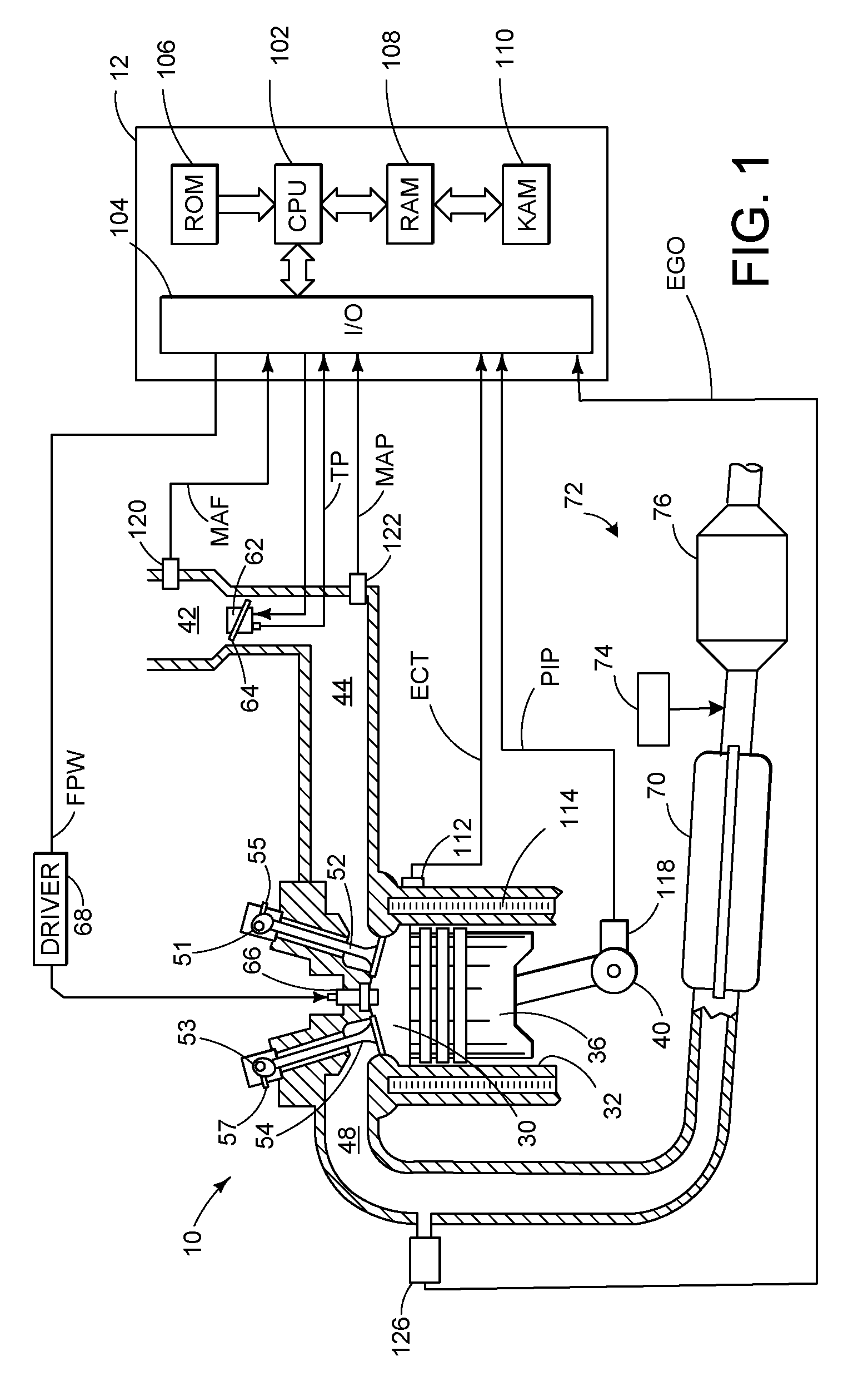
[0009]Referring now to FIG. 1, direct injection internal combustion engine 10, comprising a plurality of combustion chambers and controlled by electronic engine controller 12, is shown. Combustion chamber 30 of engine 10 includes combustion chamber walls 32 with piston 36 positioned therein and connected to crankshaft 40. In one example, piston 36 includes a recess or bowl (not shown) to form selected levels of stratification or homogenization of charges of air and fuel. Alternatively, a flat piston may also be used.

[0010]Combustion chamber 30 is shown communicating with intake manifold 44 and exhaust manifold 48 via intake valve 52, and exhaust valve 54. Fuel injector 66 is shown directly coupled to combustion chamber 30 for delivering liquid fuel directly therein in proportion to the pulse width of signal fpw received from controller 12 via conventional electronic driver 68. Fuel is delivered to fuel system (not shown) including a fuel tank, fuel pumps, and a fuel rail. In some em...


PUM


Abstract

A method of operating an internal combustion engine having a reductant delivery and storage system in an emission control system, comprising of correlating a change in a monitored operating condition with a refill event to determine whether a reductant-diluting substance has been added to the reductant storage system; and limiting vehicle operation based on the correlation.

Description

TECHNICAL FIELD[0001]The present application relates to the field of automotive emission control systems and methods.BACKGROUND AND SUMMARY[0002]Selective catalytic reduction (SCR) systems have been used to reduce automotive emissions. However, SCR systems may use a reductant, such as urea, stored in an on-board storage device that may be subject to tampering. For example, a vehicle operator may introduce an ineffective fluid to a reductant storage device.[0003]One way to detect operator tampering attaches a urea concentration sensor to a reductant storage device opening to detect the introduction of a non-urea solution (or reduced-urea solution) fluid. However, urea concentration sensors may increase vehicle cost, and may lead to still further diagnostic issues. Further, the availability of urea concentration sensors may be limited.[0004]The inventors herein have realized that a logic driven method may be implemented using existing system infrastructure to monitor reductant quality...

Claims


Application Information

Patent Timeline
IPC IPC(8): F01N3/035
CPCF01N3/208F01N9/00F01N2560/026F01N2570/145F01N2610/1406Y02T10/24F01N2900/12F01N2900/1814Y02C20/10Y02T10/47F01N2610/146Y02A50/20Y02T10/12Y02T10/40
Inventor SHAIKH, FURQAN ZAFAR ZAFARBOGEMA, JOHN PAULNIEUWSTADT, MICHIEL J. VANCOOPER, SCOTT DONALDZAWACKI, GARRY ANTHONYVISSER, JACOBUS HENDRIKRUONA, WILLIAM CHARLESWEBB, TIMOTHYKULIK, EDCHEN, DAVID K.
Owner FORD GLOBAL TECH LLC
Why Eureka
Try Eureka