Reverse Input Prevent Clutch Bearing Assembly

a technology of clutch bearings and inputs, which is applied in the direction of mechanical actuated clutches, interengaging clutches, couplings, etc., can solve the problems of bringing more expense, and reducing the overall system efficiency, so as to reduce the number of gearings and reduce the cost. , the effect of increasing the efficiency of assembly

Inactive Publication Date: 2008-07-31
BYUN DONGHWAN
View PDF5 Cites 26 Cited by
  • Summary
  • Abstract
  • Description
  • Claims
  • Application Information

AI Technical Summary

Benefits of technology

[0061]The present invention is a basic mechanical element which can be set in one unit and is divided into two types. When the back drive occurs, to prevent the back drive the locking type locks the output side while the shutoff type separates the output side from the input side. It can be classified the inner-ring control type and the outer-ring control type according to the location of the control member. It is also grouped the torque restriction type and the torque-free type according to the size of the torque when it functions as the clutch but it functions as a bearing when it does not function as the clutch.
[0062]If the rotational direction gap is fixed in the intermediate position, the present invention functions as the two-way clutch: it function as the clutch when the wedge ring restriction cam works but it functions as the bearing when the wedge ring restriction cam does not work. The present invention functions as a one-way clutch: it functions as the clutch in the rotation of the certain direction when the rotational direction gap is fixedly oriented in a certain direction, but it functions as the bearing in the opposite directional rotation of the certain direction.
[0063]The present invention can substitute for the existing bearing, the one-way clutch and the two-way clutch. It is also applied to the variety of field such as the protection of the driving device, the position maintenance of the output shaft, the braking and the idle rotation of the output shaft or the hybrid devices which use two power sources either alternatively or at the same time.
[0064]The present invention reduces half the number of the gearing because it uses the one tier gear to function as both the clutch and the bearing and reduces the cost. The efficiency to assemble is growing due to the reduction of the components. The size also is compact because the width of the bearing and the clutch components is reduced. The reverse input prevention function maximizes the efficiency of the system because the power source (e.g. the electric motor) can be reduced to the lower level to satisfy the original purpose.
[0065]We call the present invention a BUGULBA or a CLURING (clutch-bearing) because it has the bearing function and the clutch function at the same time.
[0066]The best mode below illustrates not only the structural and functional description but the desired method how to apply the best mode. It can be illustrated without changing the basic idea of this present invention. It includes every changable mode which is applicable in the scope of the described idea in the claims attached.

Problems solved by technology

There exists a possibility for damages and a segregation of components installed in the input side from the desired position by the back driving occurred in the wake of an unexpected reverse torque input from the output side.
But when the unexpected torque from the output side according to the construction of the one-way clutch happens to occur, there still exists a high probability of damaging or segregating the location of equipment installed in the prefixed location in the input side.
The goal is achieved by the negative outcome like using more driving power but reducing the overall system efficiency.
This structure consists of many small components which can bring more expense.
When the axis of the input shaft relatively mismatches to the axis of the output shaft due to the separation of the clutch, it cannot support the load.
That is, the product needs more parts to support the load which cause the increasement of the cost of production, with the number of processes to assemble increased.
Therefore not only the productivity is degraded, but also the size becomes large.

Method used


Image

  • Reverse Input Prevent Clutch Bearing Assembly
  • Reverse Input Prevent Clutch Bearing Assembly
  • Reverse Input Prevent Clutch Bearing Assembly

Examples


Embodiment Construction

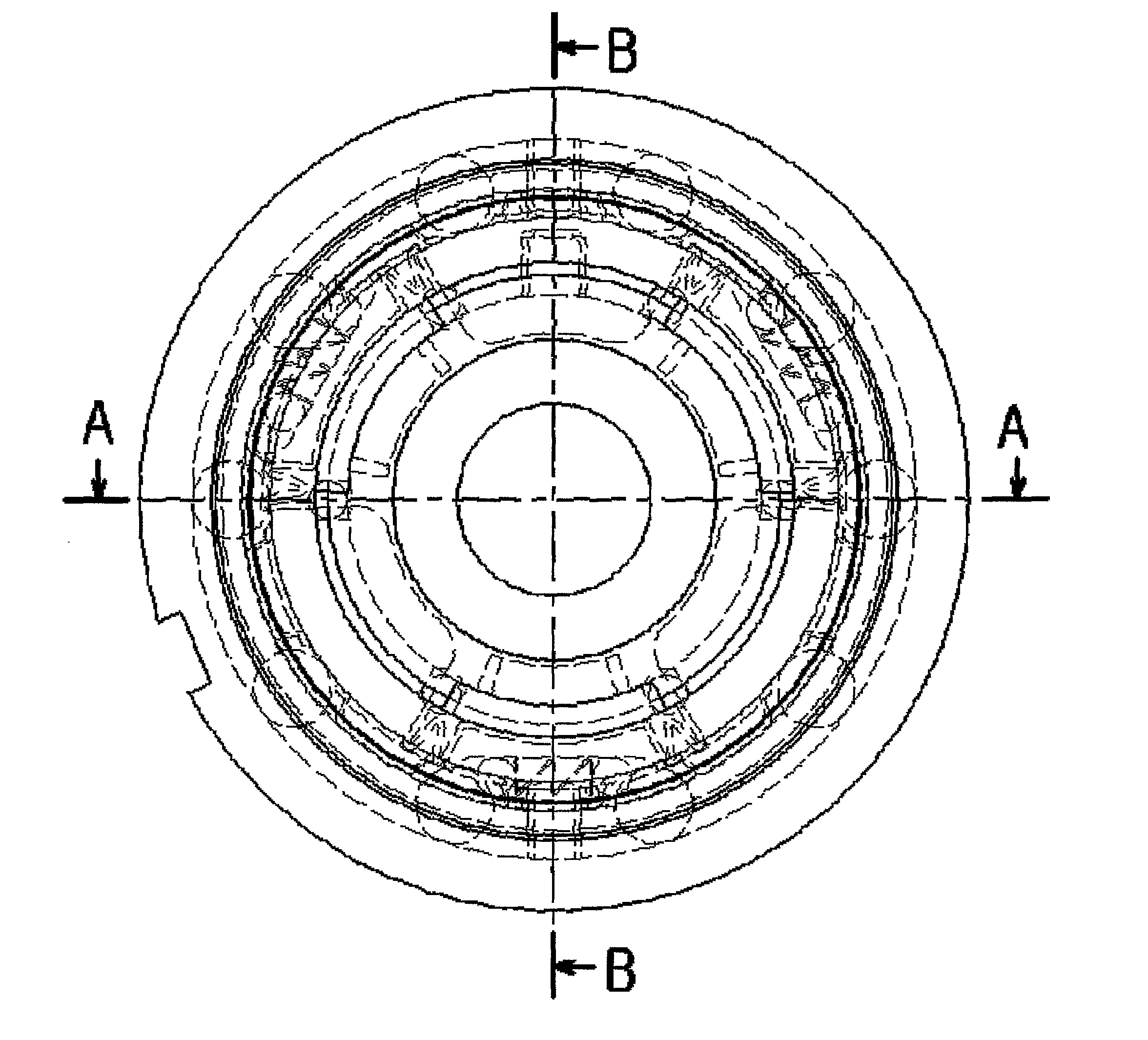
[0067]FIG. 1 is a front perspective view showing the manufactured appearance of the inner-ring control type assembly according to the desired best mode;

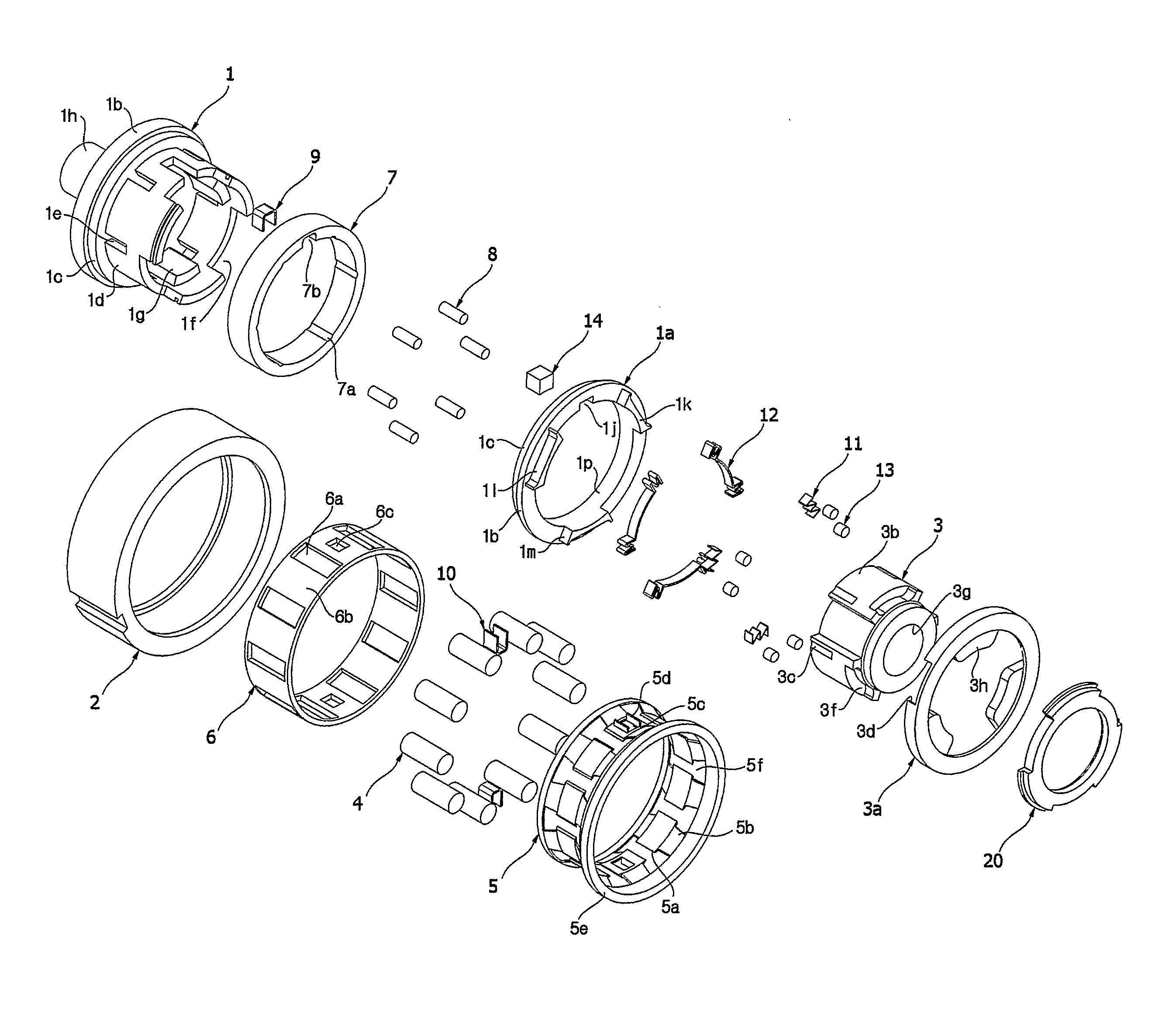
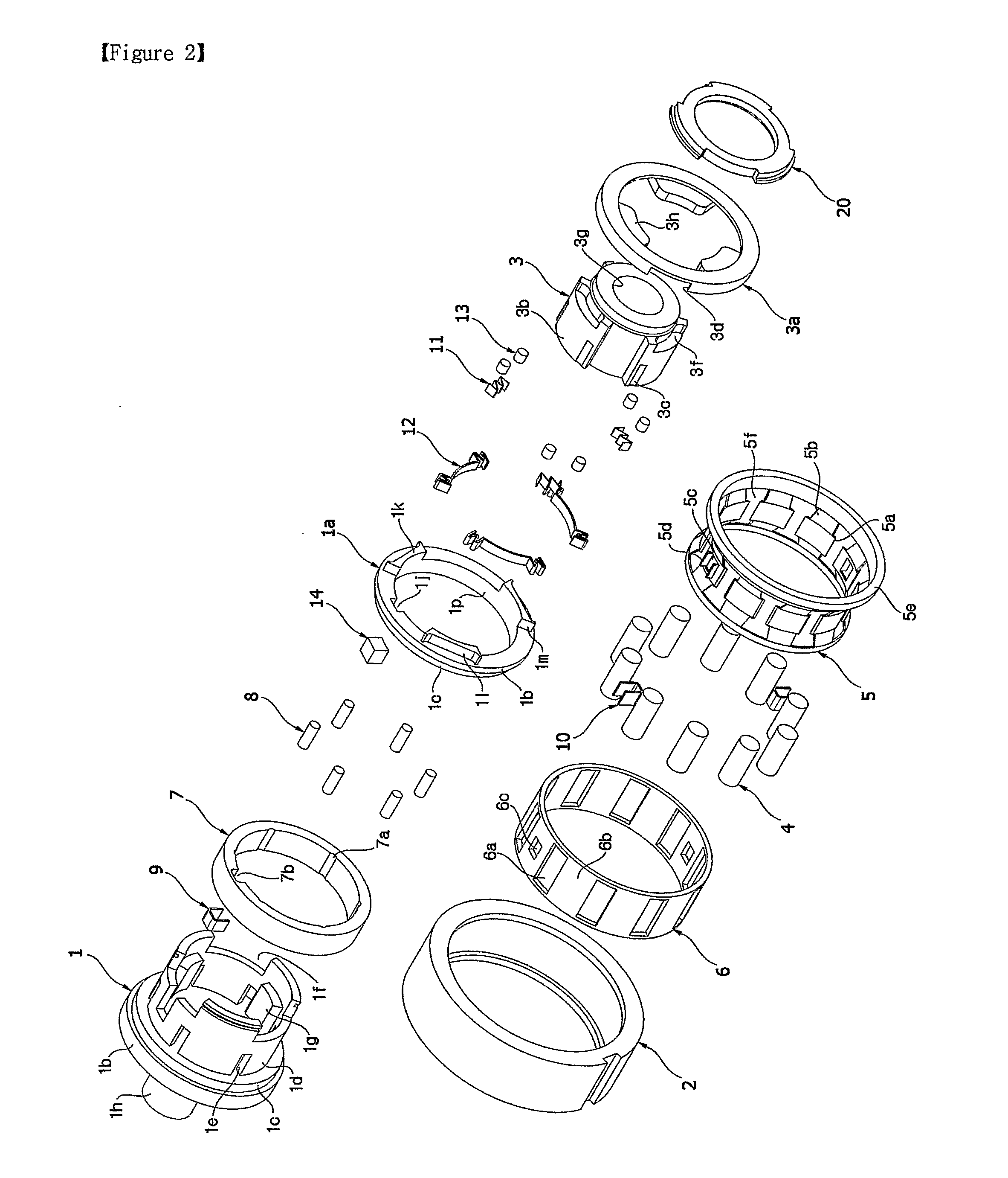
[0068]FIG. 2 is a disassembled description view showing the disassembled arrangement of every component of the inner-ring control type assembly according to the desired best mode;

[0069]FIG. 3 is a cross sectional view of the FIG. 1 along the line A-A;

[0070]FIG. 4 is a enlarged piece view showing the essential part E of the FIG. 3;

[0071]FIG. 5 is a cross sectional view of the FIG. 1 along the line B-B;

[0072]FIG. 6 is a enlarged piece view showing the essential part F of the FIG. 5;

[0073]FIG. 7 is a cross sectional view of the FIG. 3 along the line C-C;

[0074]FIG. 8 is a cross sectional view of the FIG. 3 along the line D-D;

[0075]FIG. 9 is a step-by-step situation view showing the process of the insertion and restriction and the release between the rolling members, the wedge ring and the rotational orbit member to explain the enlarged p...


PUM


Abstract

This invention presents a reverse input prevention clutch bearing assembly in which a forward and a reverse torque inputted from an input side is transmitted to a output side, while locks the transmission of the forward or the reverse torque inputted from the output side to the input side by locking the output side or by separating the output side from the input side. The reverse input prevention clutch bearing assembly has a first rotational member and a second rotational member which are arranged on a coaxial line and has orbit surfaces with different radii and a plurality of rolling members which are arranged in a circumferential shape between the two orbit surfaces so that the outer circumferential surfaces of the rolling members are contact-rotatable. The reverse input prevention clutch bearing assembly also has a cage which supports the rolling members so that the arrangement of the rolling members is maintained and a control member which has a rotational direction gap with respect to the first rotational member and is engaged with the first rotational member so that the torque of the forward and the reverse direction is transmitted with a delay by the gap. The reverse input prevention clutch bearing assembly has a distinguished wedge ring assembly which allows or does not allow the rolling members to rotate based on the change of the rotational direction gap between the first rotational member and the control member and the rotational direction of the control member. The reverse input prevention clutch bearing assembly can be used as one among a reverse input locking clutch bearing assembly, a reverse input shutoff clutch bearing assembly, a reverse input prevention two-way clutch bearing assembly, a reverse input prevention one-way clutch bearing assembly which can choose the lathing direction. The reverse input prevention clutch bearing assembly functions as the chosen clutch of the abovementioned assembly while, at the same time, functions as a bearing when the reverse input prevention clutch bearing assembly is not used as the clutch.

Description

TECHNICAL FIELD[0001]This invention is about the reverse input prevention clutch, which performs a desired operation transmitting a forward and a reverse torque input from the input side to the output side but blocks a forward or a reverse torque input from the output side by engaging the output side to the housing or separating the restriction with the driving shaft by itself without any control given from the outside.BACKGROUND ART[0002]A traditional clutch generally transmits the rotational torque by combining two (or more) broad frictional surfaces and cuts the transmission of the torque by separating frictional surfaces, or permits the rotation by separating them and cuts the rotation by combining them. This tupe clutch needs broad frictional surfaces to transmit the torque and also needs a control device, and a hydraulic device to control the operation. There exists a possibility for damages and a segregation of components installed in the input side from the desired position ...

Claims


Application Information

Patent Timeline
Patent Type & Authority Applications(United States)
IPC IPC(8): F16D41/00
CPCF16D41/066
Inventor BYUN, DONGHWAN
Owner BYUN DONGHWAN
Why Eureka
Try Eureka