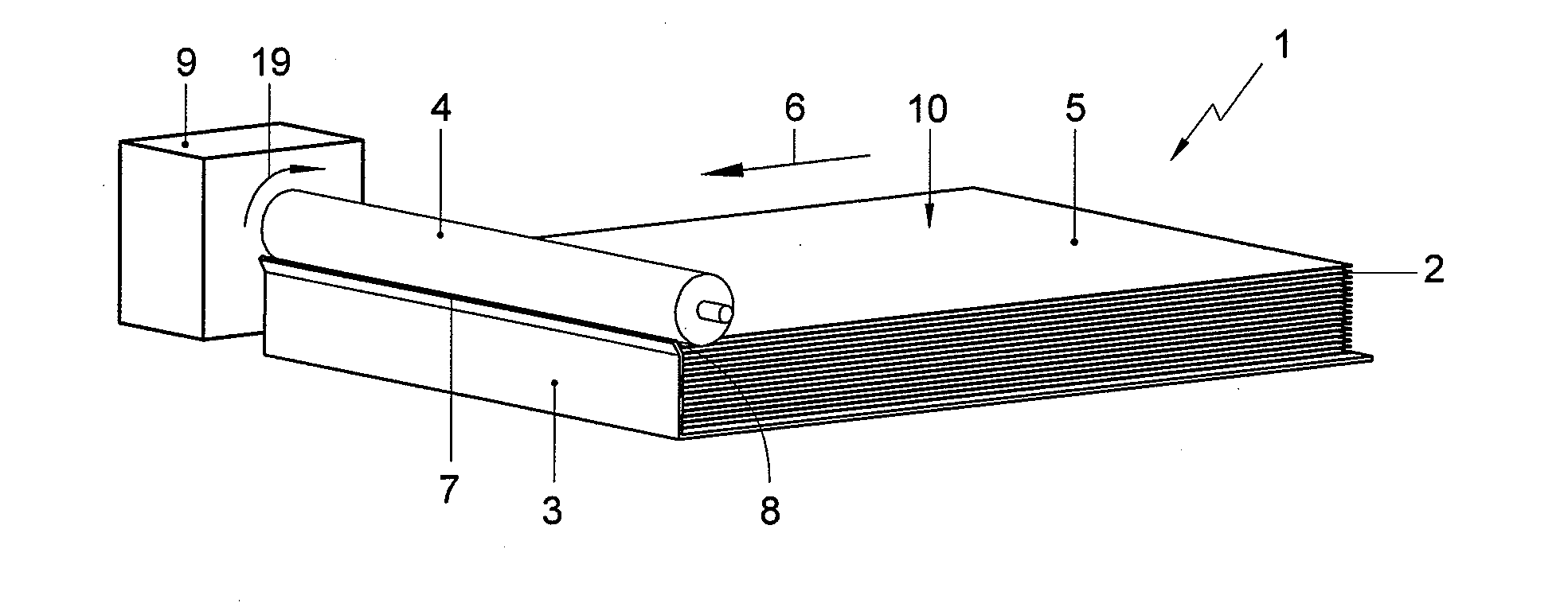
[0012]The invention is first described with reference to the example shown in FIGS. 1-3.
[0013]The separator 1 according to the present example is equipped with a holder 3 for holding a stack of envelopes 2 with an outer envelope 5 in a separating position, a feeding roller 4 and a deflecting surface 7. The feeding roller 4 and the deflecting surface 7 bound a feeding path having a width, and starting at the separating position.
[0014]The holder 3 supports the stack 2 of envelopes to be separated. The holder 3 has lateral guides 11 (not shown in FIG. 1) for maintaining the envelopes positioned by contacting lateral edges of the envelopes. The guides 11 are adjustable in the lateral direction by rotating a threaded spindle 12, for adapting the mutual distance between the guides 11 to envelopes of different sizes. Stops 13 define the maximum outer position of the guides 11.
[0015]The stack of envelopes 2 is positioned with one edge against a front (downstream) wall of the holder 3 for aligning the envelopes in relation to the feeding roller 4 and the deflecting surface 7 and for refraining the envelopes from displacement in transport direction 6.
[0016]The holder 3 is may be positioned in an inclined orientation, such that the stack of envelopes is leans against the front wall of the holder by gravity.
[0017]The holder 3 is provided with a moveable bottom surface and with a biasing member (not shown) for urging the stack 2 against the feeding roller 4 while maintaining the outer envelope 5 generally in the separating plane 10. Thus, the outer envelope 5 of the stack 2 is brought in a separating position in a separating plane 10 at the top of the stack 2, and is positioned with its leading edge 8 just above the front wall of the holder 3 and near the deflecting surface 7.
[0018]The feeding roller 4 has a circumference and is positioned relative to the holder 3 for contacting the envelope 5 in a contact area of its circumference. The feeding roller 4 extends from beyond opposite lateral sides of the feeding path inwardly. It therefore contacts the envelope 5 in side areas 15, 16 along opposite side edges of the envelope 5.
[0019]Spaced from the contact position between feeding roller 4 and the envelope 5, the deflecting surface 7 is positioned, preferably as a continuation of the wall of the holder 3. As the feeding roller 4, the deflecting surface 7 extends in lateral direction from beyond the lateral sides of the feeding path inwardly across lateral outer portions of the feeding path.
[0020]In the embodiment shown, the feeding roller 4 and the deflection surface 7 both extends continuously from one lateral side of the feeding path inwardly across the feeding path to the other, opposite lateral side of the feeding path. In alternative embodiment, shown in FIG. 4, feeding rollers 24 and deflection surfaces 27 of a separator 21 extend along outer zones of the feeding path only.
[0021]Returning to the separator according to FIGS. 1-3, the feeding roller 4 is connected to a drive 9 for driving rotation of the roller 4 about a heart line thereof. When the roller 4 is rotated, a friction force is exerted onto the outer envelope 5 and urges the envelope in a feeding direction 6 tangential to the circumference of the feeding roller 4 and parallel to the separating plane 10.
[0022]For separating the envelope 5 from the stack 2, the feeding roller 4 is driven by the drive 9 in a sense of rotation indicated by an arrow 19, exerting a friction force onto the outer envelope 5 in the separating position in the feeding direction 6 tangential to the feeding roller 4 and parallel to the separating plane 10. This causes the outer envelope 5 to be displaced in the separating plane 10 along the feeding path in the feeding direction 6 and causes the leading edge 8 of the envelope 5 to be urged against the deflecting surface 7 located downstream in the feeding direction 6 of the contact area of the circumference of the feeding roller 4. Accordingly, the outer envelope 5 encounters resistance depending on the bending stiffness of the envelope 5 and increasing as the envelope is bent.
[0023]However, the friction force exerted by the feeding roller 4 onto the envelope 5 causes the envelope to be urged along the deflecting surface 7, which causes the envelope to bend out of the separating plane 10 as it is urged along the deflecting surface 7. The circumferential surface of the feeding roller 4 has a friction coefficient relative to paper that is larger than the friction between the envelope in the separating position and the next envelope in the stack of envelopes 2. The maximum friction force exerted on the next envelope in the stack 2 is therefore lower than the maximum friction force the feeding roller 4 can exert on the outer envelope 5 and insufficient for overcoming the resistance encountered when urged against the deflecting surface 7.
[0024]Since the feeding roller 4 and the deflection surface 7 engage the outer envelope 5 in its lateral side areas 15, 16, which are the stiffest areas of the envelope, a relatively high resistance is encountered when the outer envelope 5 contacts the deflection surface 7. This resistance can be overcome easily by the fraction force exerted by the feeding roller 4, but reliably refrains a next envelope, similarly subjected to bending forces in edge areas where it is relatively stiff, from being entrained by the outer envelope 5.
[0025]Furthermore, by bending the envelope along its side edges, it is ensured that envelope is bent over its entire width and not only in the more flexible centre part.
[0026]Since the feeding roller 4 and the deflection surface 7 extend across the feeding path without interruption, the effect of engaging envelopes in areas along the side edges is achieved for envelopes of widely varying sizes and the bending stiffness of the envelopes is used over the entire width of the envelope.
[0027]The deflecting surface 7 extends at an angle to the separating plane. The angle between the deflecting surface 7 and the separating plane is selected such that an outer envelope 5 entrained by the rotating feeding roller 4 is urged past the deflecting surface, whereas friction forces between envelopes, by which a next envelope is entrained are insufficient to overcome the resistance the next envelope encounters when it is deflected by the deflection surface. In practice, the angle between the deflecting surface and the separating plane is preferably between 85 and 140° and more preferably between 110 and 130°.
[0028]When envelopes of different width are processed, the relatively stiff side edge areas of the envelopes engage different sections of the deflection surface. By providing that the deflecting surface has a friction coefficient that is uniform across its width, the resistance encountered by envelopes being separated varies only little with width of the envelopes of the envelopes.
[0029]The friction coefficient of the deflecting surface relative to paper is preferably smaller than the friction coefficient between rubber and paper, which is about 1. More preferably, the friction coefficient of the deflecting surface relative to paper is smaller 0.8, so that it is smaller than the friction coefficient between rubber and paper by a substantial amount.
[0030]The friction coefficient of the deflecting surface relative to paper is preferably larger than the friction coefficient between metal and paper, which is about 0.1. to 0.4. More preferably, the friction coefficient of the deflecting surface relative to paper is larger than 0.5 or, more preferably, 0.6, so that it is smaller than the friction coefficient between metal and paper and larger than the friction coefficient between envelopes by a substantial amount.
[0031]The bending distance, that is the distance between the point of contact area of the circumference of the feeding roller 4 and the most remote point of contact between the envelope being separated and the deflecting surface 7, is preferably between 6 and 12 mm, and more preferably between 7.5 and 10.5 mm, for a feeding roller 4 having a diameter of 25 mm.
[0032]Once the leading edge 8 of the envelope 5 is deflected out of the separating plane 10, the leading edge 8 is for example led into a nip of a transport track 14 formed by pairs of opposite conveyor belts.
[0033]Other variations to the disclosed embodiments can be understood and effected by those skilled in the art in practicing the claimed invention, from a study of the drawings, the disclosure, and the appended claims.