

Vehicle wheel and manufacturing method of the same
- Summary
- Abstract
- Description
- Claims
- Application Information
AI Technical Summary
Benefits of technology
Problems solved by technology
Method used
Image

Examples
Embodiment Construction
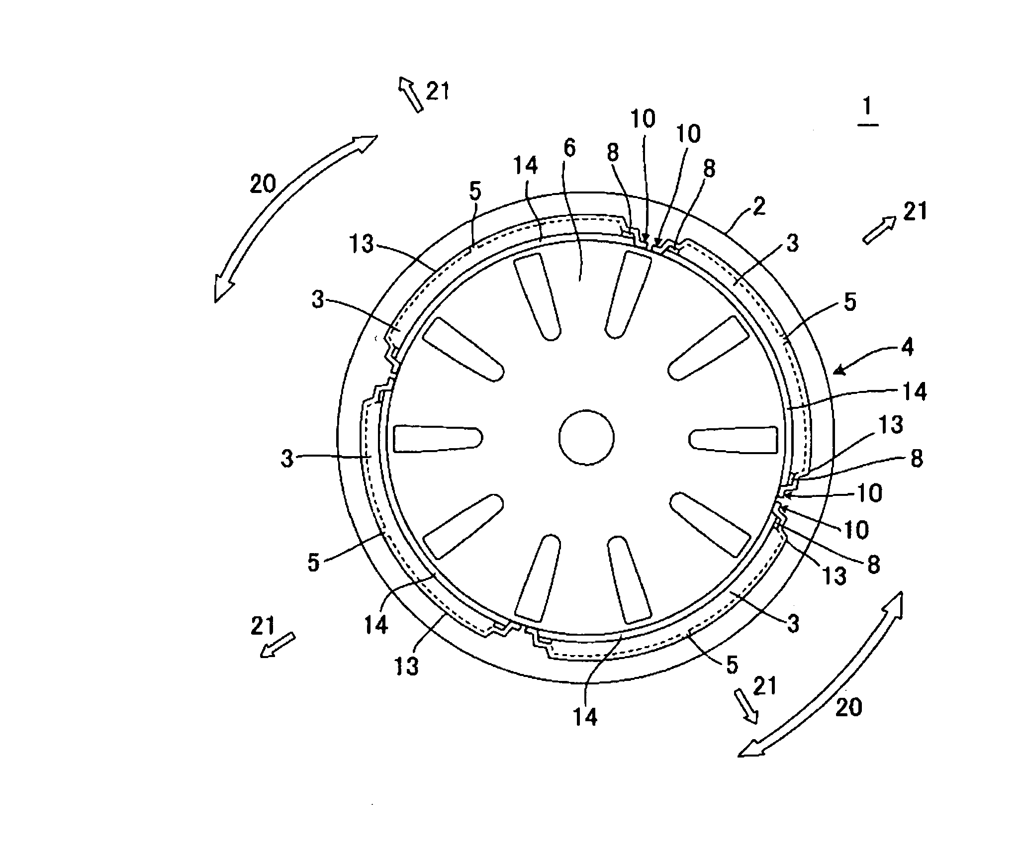
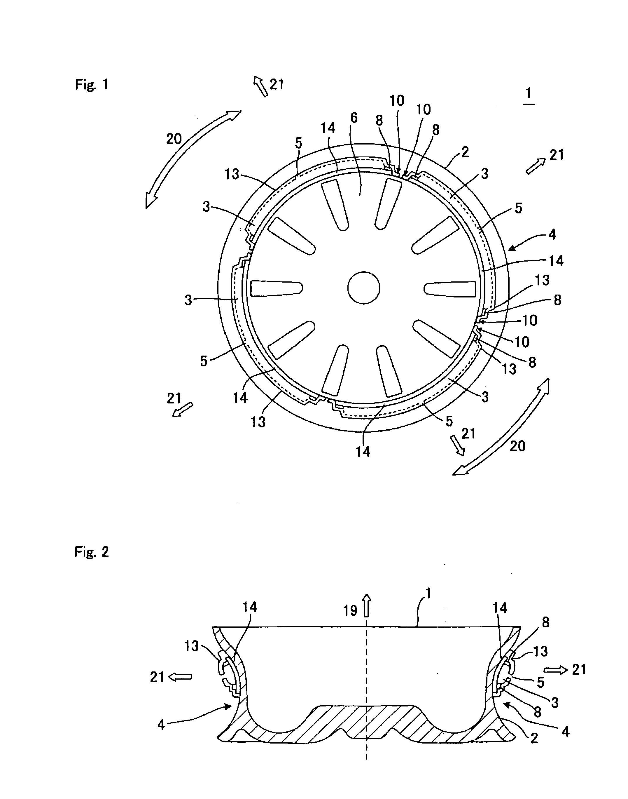
[0085]The vehicle wheel according to the present invention incorporates subsidiary air chambers on the outer peripheral surface of the rim thereof, each of the subsidiary air chambers being formed at least in part by a cover member which ensures at the peripheral part air-tightness so as to form a subsidiary air chamber having air-tightness.
[0086]In the vehicle wheel according to the present invention, a plurality of subsidiary air chambers are preferably formed on the outer peripheral surface of the rim.
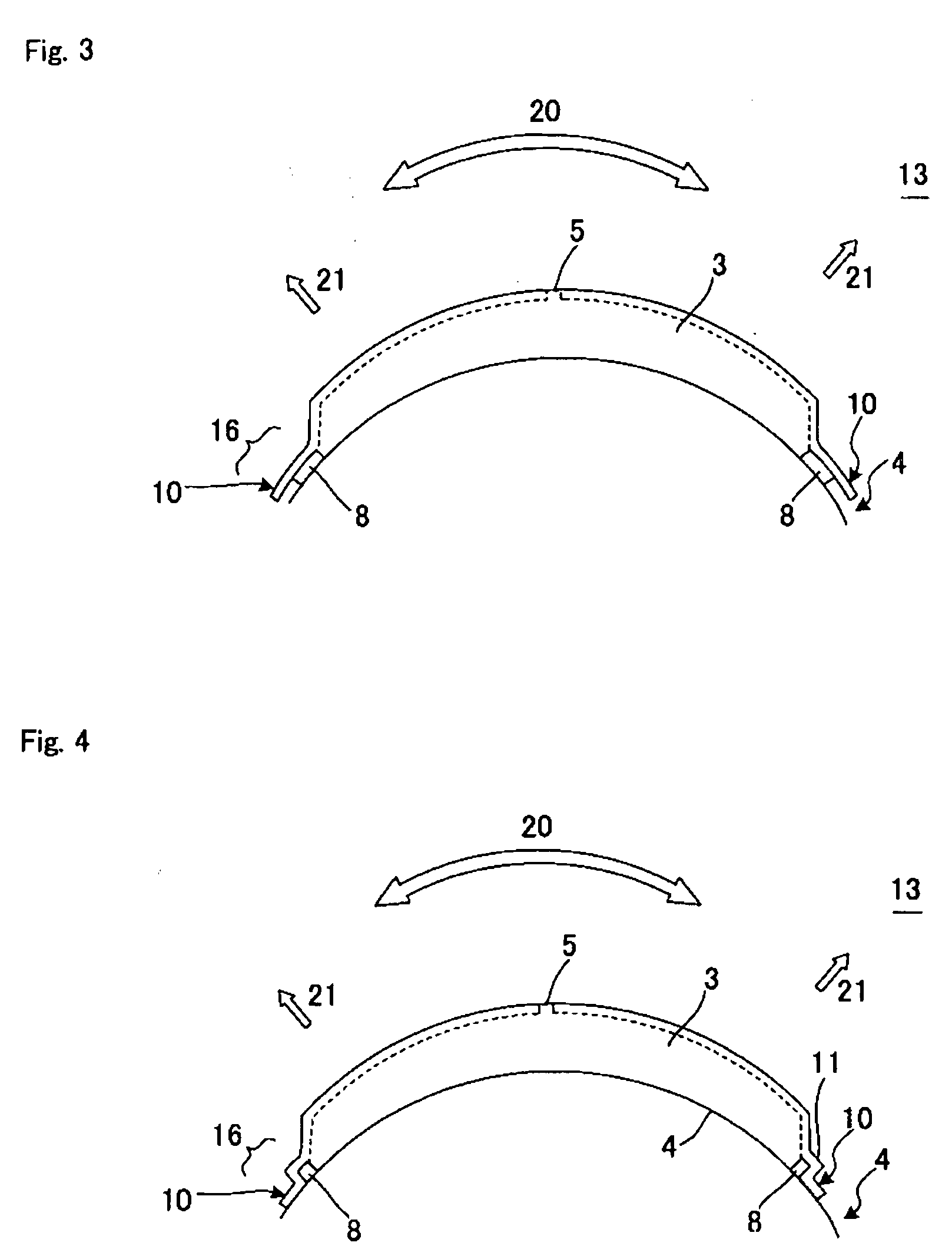
[0087]In the vehicle wheel according to the present invention, the cover member preferably has a lug part at least around the part of the periphery, and the lug part and the outer peripheral surface of the rim are joined to each other in an airtight manner so as to form a subsidiary air chamber having air-tightness on the outer peripheral surface of the rim.
[0088]In the vehicle wheel according to the present invention, a seal member is preferably interposed between the cover member ...
PUM
| Property | Measurement | Unit |
|---|---|---|
| Thickness | aaaaa | aaaaa |
| Elasticity | aaaaa | aaaaa |
Abstract
Description
Claims
Application Information