Platen retaining structure and recording unit

a technology of retaining structure and plate, which is applied in the direction of measuring devices, instruments, printing, etc., can solve the problems of deteriorating space efficiency, inability to detect position, and inability to provide the switch used for position detection on the head sid

Inactive Publication Date: 2008-07-31
SEIKO INSTR INC
View PDF5 Cites 26 Cited by
  • Summary
  • Abstract
  • Description
  • Claims
  • Application Information

AI Technical Summary

Benefits of technology

[0020]According to the present invention, it is possible to realize a versatile recording unit which can be used for both of the recording unit having the construction in which a part of the platen and the platen frame is to be exposed to the exterior of the casing, and the recording unit having the construction in which the platen and the platen frame are not to be exposed to the exterior of the casing. In the recording unit, only by the switch used for position detection, which detects the movement of the platen or the release arm, the relative positional relationship between the head and the platen can be detected in both types of the recording unit.

Problems solved by technology

Conventionally, in the construction in which the platen frame is not moved, the platen is not moved either, and a movable member like the release arm does not exist, so the position detection is impossible.
Therefore, in order to judge whether the recording unit is in a recordable state or not, the switch used for position detection cannot be avoided to be provided on the head side.
As a result, the construction is disadvantageous in that the space efficiency deteriorates.

Method used


Image

  • Platen retaining structure and recording unit
  • Platen retaining structure and recording unit
  • Platen retaining structure and recording unit

Examples


Embodiment Construction

[0029]Hereinafter, an embodiment mode of the present invention will be described with reference to the drawings.

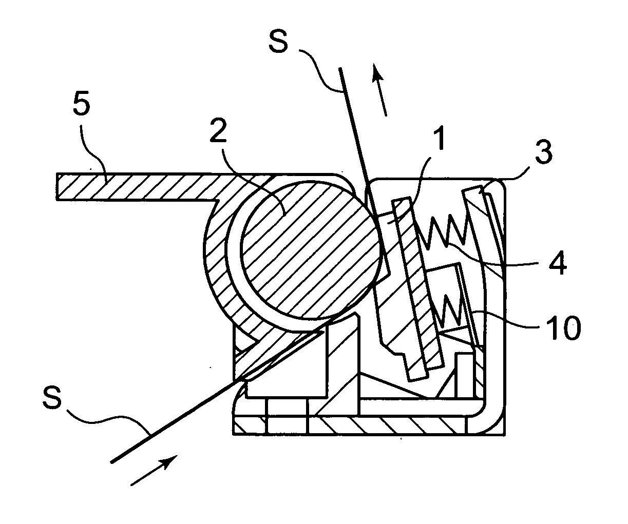
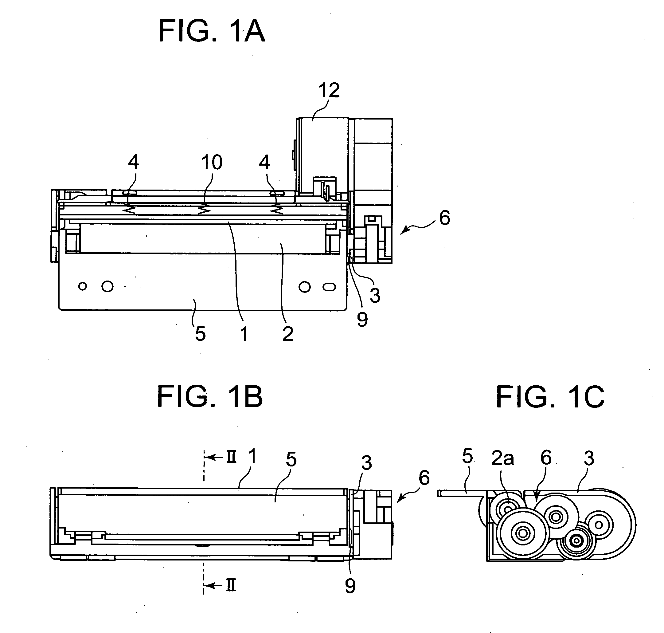
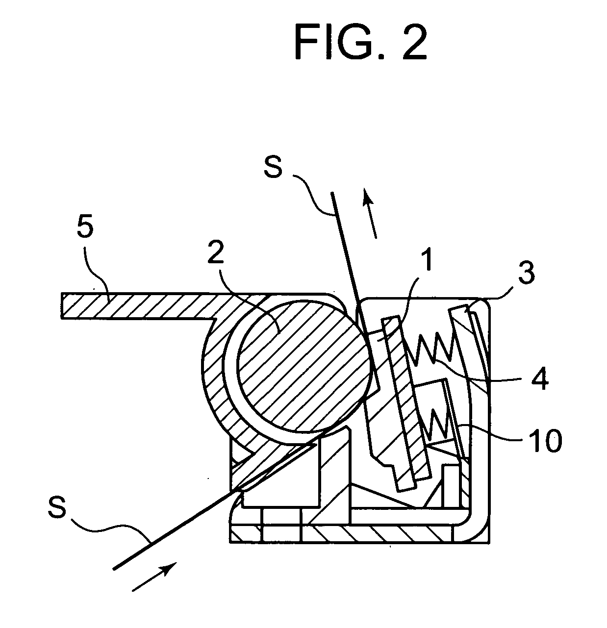
[0030]FIGS. 1A-1C and 2 show a main part of a recording unit in which a recording unit according to an embodiment of the present invention is contained. In the recording unit, which is in a recordable state, a thermal head 1 which is an example of a recording head for performing recording on a recording medium (sheet material) S as shown in FIG. 2, and a roller-type platen (platen roller 2) for transporting the recording medium S are arranged to be adjacent to each other. Although not shown in the figure, the thermal head 1 includes a large number of heat generating elements and an electrical connection mechanism for transmitting drive signals so as to selectively drive the heat generating elements. Between the thermal head 1 and the frame 3, there is provided a spring member 4 serving as a first urging means for urging the thermal head 1 to be in press contact with the pl...


PUM


Abstract

A shaft portion 2a of a platen roller 2 is inserted into an elongated hole-like recess 5a of a platen frame 5 so as to be movable therein. A release arm 9 having an engagement portion 9b engaged with a shaft portion 2a is swingably provided and is urged by a spring member 10. A switch 11 has an intercept 11a which can be contacted/separated to/from the release arm 9. When a thermal head 1 is moved against a spring force of a spring member 4, the release arm 9 follows the thermal head 1 to be allowed to swing by the spring member 10, thereby moving the shaft portion 2a in the recess 5a. When the switch 1 detects movement of the release arm 9, it is determined that recording is impossible since the thermal head 1 and the platen roller 2 are spaced apart from each other.

Description

FIELD OF THE INVENTION[0001]The present invention relates to a retaining structure for a platen roller used at a position in contact with a head, and a recording unit including the same.DESCRIPTION OF THE RELATED ART[0002]Conventionally, there is a recording unit having inside a casing a recording head and a roller-type platen (platen roller.) being in contact therewith, with the recording head performing recording on a recording medium (sheet material) transported by the platen roller. In general, the recording head and the platen roller are fixed to be held in contact with each other, and during recording, the recording medium is inserted between the recording head and the platen roller, and recording is performed by the recording head while transporting the recording medium through rotation of the platen roller. In the recording unit, in a case of performing operations such as setting of the recording medium by inserting it between the recording head and the platen roller, jam tr...

Claims


Application Information

Patent Timeline
Patent Type & Authority Applications(United States)
IPC IPC(8): G01D15/00
CPCB41J2/32B41J2202/31B41J11/14B41J11/04B41J11/006
Inventor TAKAHASHI, MASANORI
Owner SEIKO INSTR INC
Why Eureka
Try Eureka