Lens actuator, and electronic device using the same

a technology of actuators and actuators, applied in the field of lenses actuators, can solve problems such as destabilizing connections, and achieve the effects of less time and effort, and reduced siz

Inactive Publication Date: 2008-07-31
PANASONIC CORP
View PDF5 Cites 23 Cited by
  • Summary
  • Abstract
  • Description
  • Claims
  • Application Information

AI Technical Summary

Benefits of technology

[0022]In this structure, the coil is disposed in the fixed part. Thus, this structure can provide an electronic device including a lens actuator in which the ends of the coil need not have a slack, and treatment of both ends of the coils and assembly take less time and effort. The coil and magnet are faced with each other, the magnet is magnetized in the optical axis direction of the lens, and the pair of magnetic materials is disposed at both ends of the magnet in the optical axis direction, to direct the magnetic flux toward the coil. With this structure, a clearance need not be provided at both ends of the coil in the radial direction thereof, unlike the conventional structure. The necessary clearance is only the clearance provided between the magnet and the coil. Thus, an electronic device including a lens actuator, capable of automatic focus operation that can be downsized in the radial direction can be provided.
[0023]As described above, the present invention can provide a lens actuator and electronic device in which the size can be reduced in the radial direction, treatment of both ends of the coil and assembly take less time and effort, and repeated operations cause no unstable connections.

Problems solved by technology

Repeated operations may cause breaks, thus destabilizing these connections.

Method used


Image

  • Lens actuator, and electronic device using the same
  • Lens actuator, and electronic device using the same
  • Lens actuator, and electronic device using the same

Examples


Embodiment Construction

[0033]Hereinafter, a description is provided of exemplary embodiments of the present invention, with reference to FIGS. 1 through 6.

Exemplary Embodiment

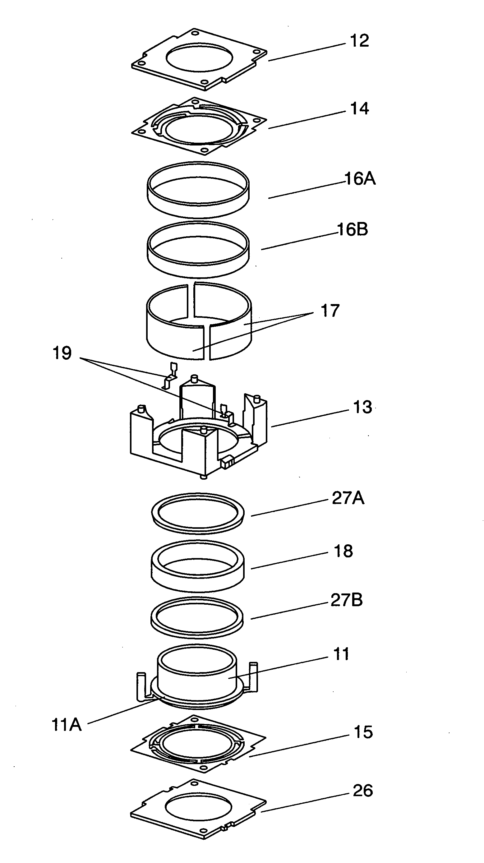
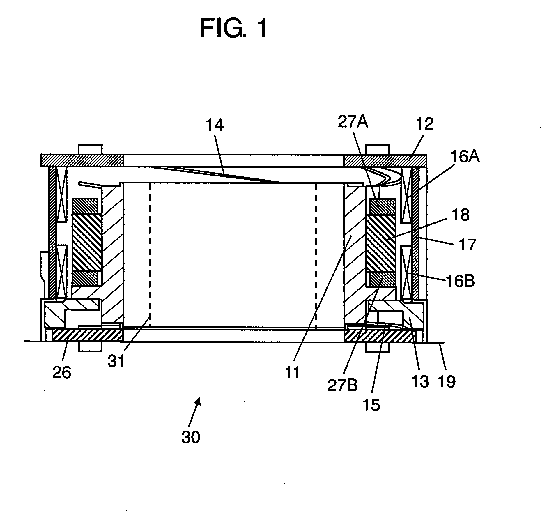
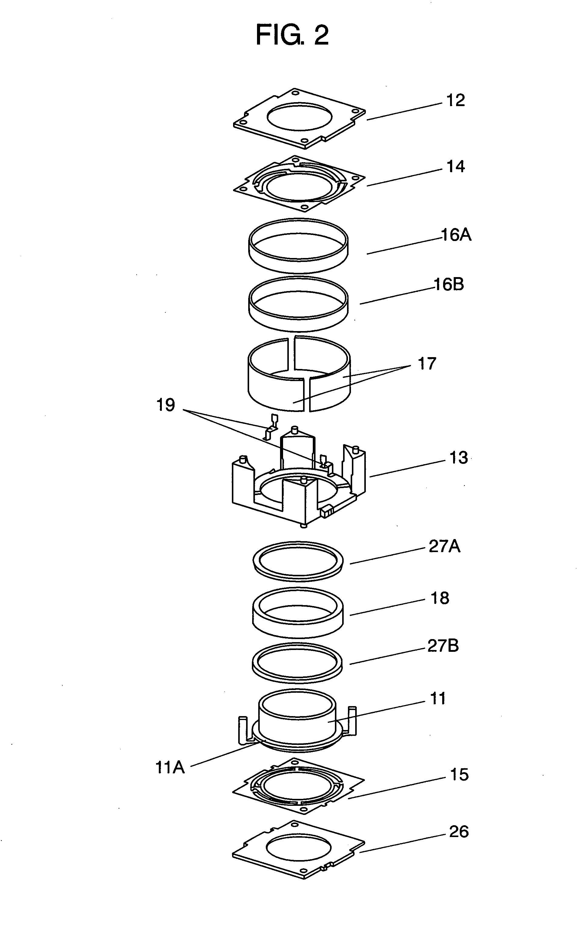
[0034]FIG. 1 is a sectional view of lens actuator 30 in accordance with the exemplary embodiment of the present invention. FIG. 2 is an exploded perspective view of lens actuator 30. With reference to FIGS. 1 and 2, lens actuator 30 includes substantially cylindrical carrier 11 made of insulating resin, e.g. polycarbonate including glass; top cover 12 made of insulating resin, e.g. polybutylene terephthalate; and case 13 made of similar insulating resin.

[0035]Lens 31 (not shown in FIG. 2) is fitted in a hollow portion of carrier 11. Carrier 11 is housed between case 13 and top cover 12 covering the top face of the case so as to be movable vertically. Further, to the bottom face of case 13, bottom cover 26 is attached.

[0036]In lens actuator 30 of this exemplary embodiment, carrier 11, i.e. a movable part, moves with respect to case 13...


PUM


Abstract

A lens actuator is provided for moving a movable part including a lens, with respect to a fixed part in the optical axis direction of the lens. The lens actuator includes (a) a magnet disposed on the surface of the movable part facing the fixed part and magnetized in the optical axis direction, (b) a coil disposed on the surface of the fixed part facing the magnet, and (c) a pair of magnetic materials disposed on both sides of the magnet in the optical axis direction, to direct magnetic flux from the magnet toward the coil.

Description

BACKGROUND OF THE INVENTION[0001]1. Field of the Invention[0002]The present invention relates to a lens actuator for moving a lens, and to an electronic device using the lens actuator, such as a camera and a portable telephone.[0003]2. Background Art[0004]In recent years, an increasing number of electronic devices incorporating a lens, such as a camera and a portable telephone, have been making auto-focusing operation of the lens, using a lens actuator. In association with this, with the downsizing of the electronic devices, lens actuators that can be downsized and operated in a stable manner are required. Such conventional lens actuator 130 is described with reference to FIGS. 7 through 9.[0005]FIG. 7 is a sectional view of conventional lens actuator 130. FIG. 8 is an exploded perspective view of lens actuator 130. As shown in FIGS. 7 and 8, lens actuator 130 includes substantially cylindrical carrier 111 made of insulating resin, cover 112 made of insulating resin, and case 113 ma...

Claims


Application Information

Patent Timeline
Patent Type & Authority Applications(United States)
IPC IPC(8): G02B7/04
CPCG03B13/36G02B7/08
Inventor SATA, NORIFUMIINOUE, TAKEFUMIKIMOTO, SHINSUKEWATADA, MASAYA
Owner PANASONIC CORP
Why Eureka
Try Eureka