Method and apparatus to monitor a temperature sensing device

a technology of temperature sensing device and temperature sensing device, which is applied in the direction of instruments, heat measurement, calorimeters, etc., can solve the problems of consuming operating space, memory and execution time in the control module, inability to monitor the temperature, and inability to accurately read the temperatur

Active Publication Date: 2008-07-31
GM GLOBAL TECH OPERATIONS LLC
View PDF16 Cites 182 Cited by
  • Summary
  • Abstract
  • Description
  • Claims
  • Application Information

AI Technical Summary

Benefits of technology

[0007]In accordance with an embodiment of the invention, a method and an article of manufacture are provided to monitor a temperature sensing circuit and detect a fault therein. The method comprises monitoring sensor readings output from a plurality of temperature sensing circuits. An average sensor reading is determined, calculated from the sensor readings output from a subset of the temperature sensing circuits. Each of the sensor readings is compared to the average sensor reading. A fault is identified when one of the sensor readings deviates from the average sensor reading by an amount greater than a threshold, more particularly when one of the sensor readings deviates from the average sensor reading by an amount greater than the threshold at least a quantity of X times out of Y sensor readings.

Problems solved by technology

These systems and devices for monitoring temperature may have faults which lead to incorrect readings of temperature, and are often required to be monitored.
This approach requires engineering effort to develop and calibrate the predictive model, and consumes operating space, memory and execution time in the control module.
A risk of executing a temperature rationality monitor includes occurrence of a falsely indicated fault, wherein a system inaccurately identifies presence of a fault, and can be caused by executing the temperature rationality monitor during extreme environmental conditions, or electrical circuit noise, or errors in digital signal processing.
One method to address such concerns includes limiting operating conditions as which rationality tests can be conducted, which results in reduced signal resolution, or reduced temperature sensing range.

Method used


Image

  • Method and apparatus to monitor a temperature sensing device
  • Method and apparatus to monitor a temperature sensing device
  • Method and apparatus to monitor a temperature sensing device

Examples


Embodiment Construction

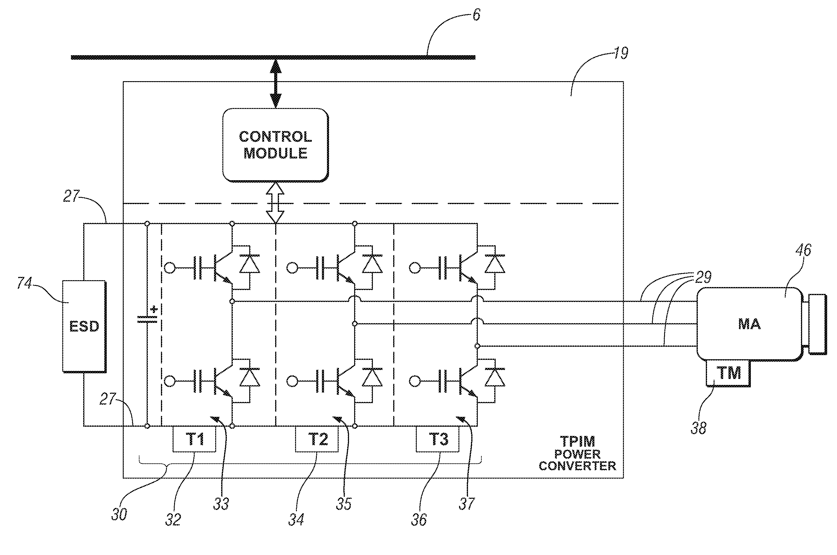
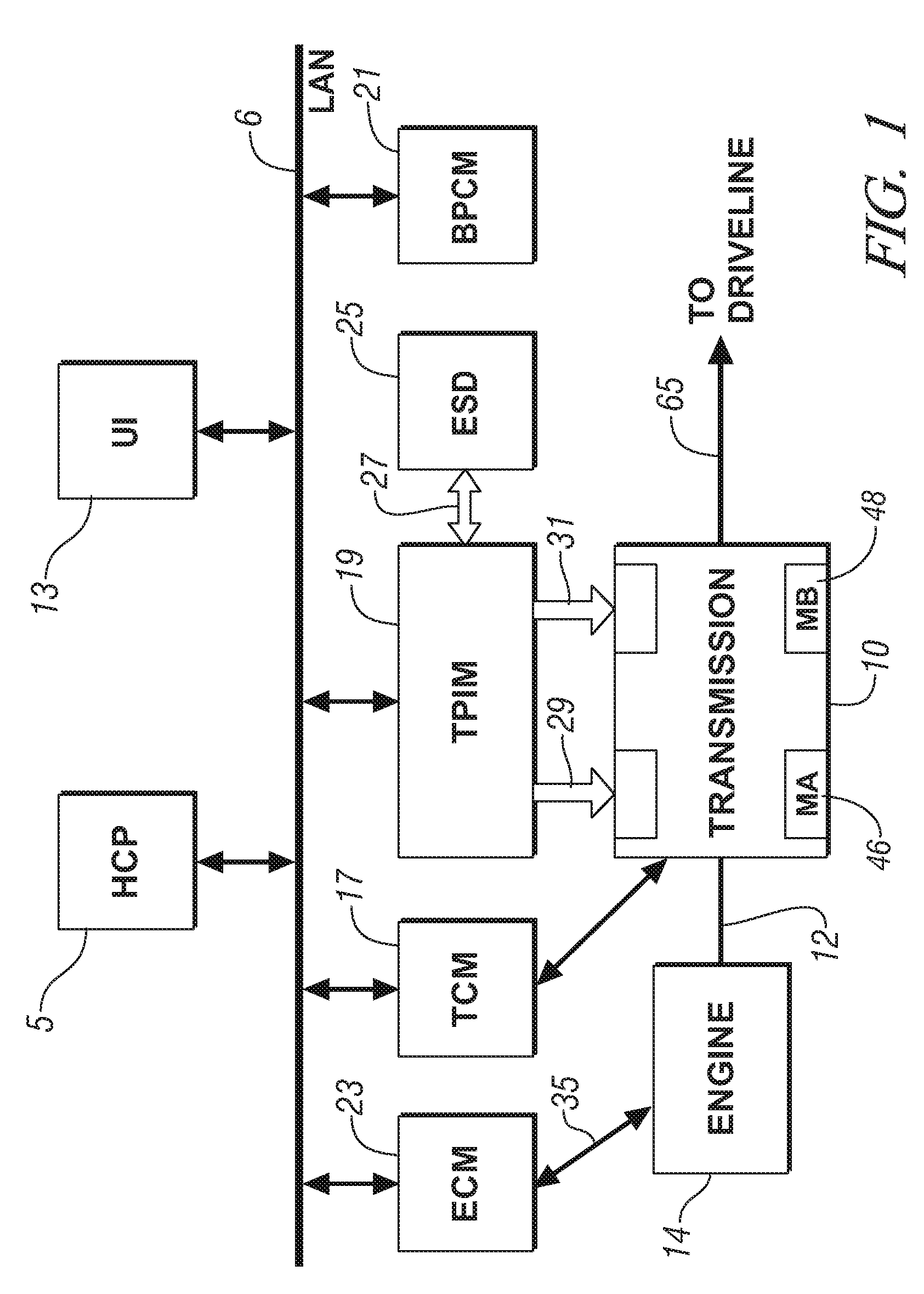
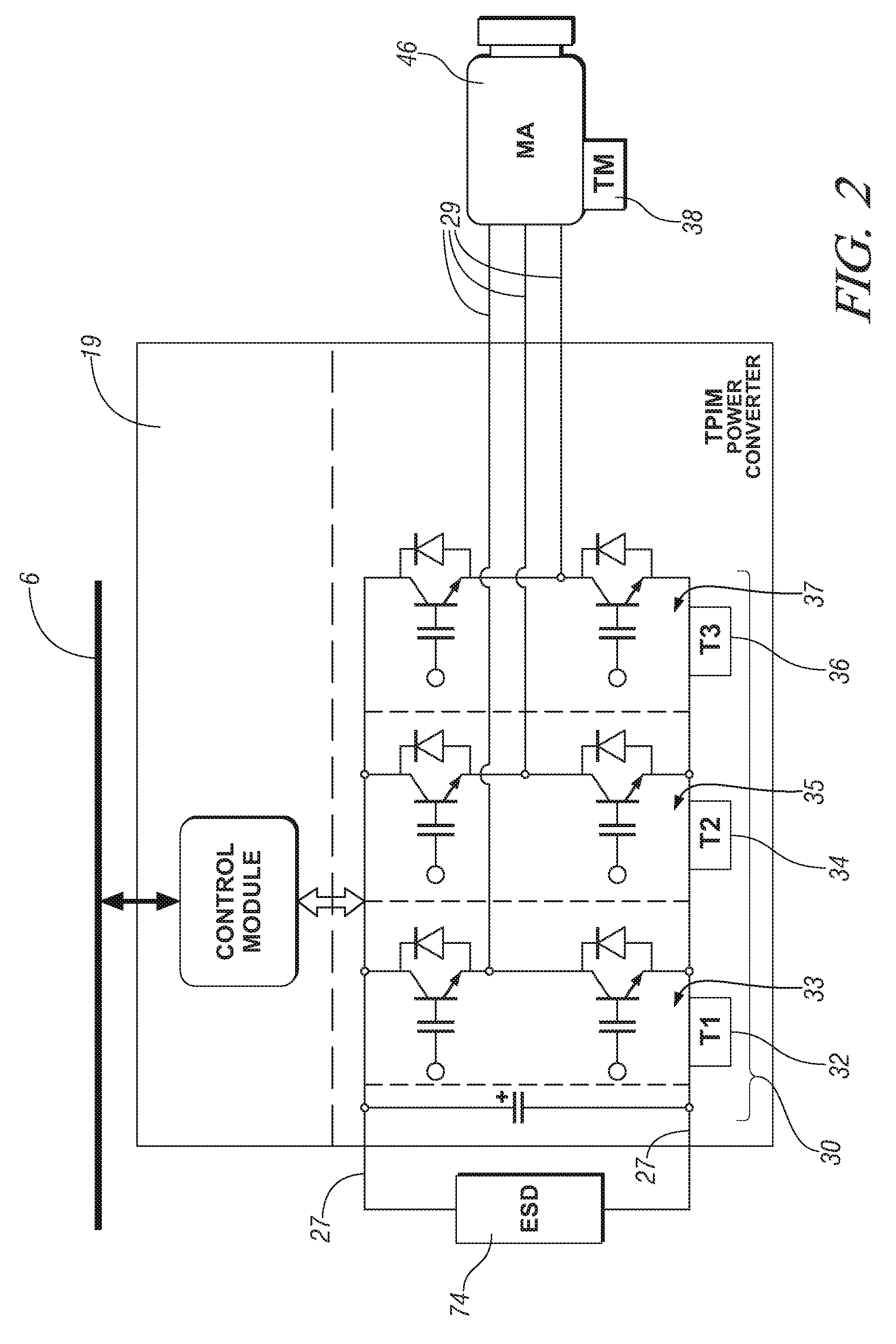
[0013]Referring now to the drawings, wherein the showings are for the purpose of illustrating the invention only and not for the purpose of limiting the same, FIGS. 1 and 2 depict schematic diagrams of a powertrain control system which has been constructed in accordance with an embodiment of the invention. The elements described hereinafter are operable to provide coordinated control of the powertrain system described herein. The powertrain comprises an internal combustion engine 14 and an electro-mechanical transmission 10 operative to provide a torque output to a driveline via an output shaft 65. The electromechanical transmission 10 includes a pair of electrical machines MA, MB 46, 48. The engine, transmission, and electrical machines are operative to transmit torque therebetween according predetermined control schemes and parameters not discussed in detail herein.

[0014]In the embodiment depicted, the transmission 10 receives input torque from the torque-generative devices, inclu...


PUM

PropertyMeasurementUnit
thresholdaaaaaaaaaa
temperaturesaaaaaaaaaa
temperatureaaaaaaaaaa

Abstract

A method and an article of manufacture are provided to monitor a temperature sensing circuit and detect a fault therein. The method comprises monitoring sensor readings output from a plurality of temperature sensing circuits. An average sensor reading is determined, calculated from the sensor readings output from a subset of the temperature sensing circuits. Each of the sensor readings is compared to the average sensor reading. A fault is identified when one of the sensor readings deviates from the average sensor reading by an amount greater than a threshold, more particularly when one of the sensor readings deviates from the average sensor reading by an amount greater than the threshold at least a quantity of X times out of Y sensor readings.

Description

TECHNICAL FIELD[0001]This invention pertains generally to powertrain control systems and systems for detection of faults therein.BACKGROUND OF THE INVENTION[0002]Powertrain control architectures include systems for monitoring operation of various components and subsystems to ensure proper control and operation, and to identify component and system faults. This includes devices and control algorithms operative to monitor temperatures of some of the components and subsystems. Temperature monitoring can be accomplished using systems having temperature sensing devices, including circuits which utilize thermo-resistive devices, e.g., thermistors and other sensors. These systems and devices for monitoring temperature may have faults which lead to incorrect readings of temperature, and are often required to be monitored.[0003]Monitoring of temperature sensing systems includes systems operative to detect electrical shorts and open circuits. Monitoring can include rationality monitors, where...

Claims


Application Information

Patent Timeline
Patent Type & Authority Applications(United States)
IPC IPC(8): G01K15/00
CPCG01K15/007G01K15/00
Inventor WANG, WEI D.WU, PETER E.GATARIC, SLOBODANWEST, STEPHEN T.BAUER, HARRY J.
Owner GM GLOBAL TECH OPERATIONS LLC
Why Eureka
Try Eureka