Television receiver apparatus and a frame-rate converting method for the same

Inactive Publication Date: 2008-07-31
HITACHI LTD
View PDF1 Cites 30 Cited by
  • Summary
  • Abstract
  • Description
  • Claims
  • Application Information

AI Technical Summary

Benefits of technology

[0007]Then, according to the present invention, accomplished by taking the drawback within the conventional art mentioned above into the consideration thereof, and namely, an object of the present invention is to provide a television rece

Problems solved by technology

As was mentioned above, in case when displaying the still picture piling on the moving picture, in particular, when conducting a frame-rate conversion process upon the video signal, which is obtained by piling up the still pi

Method used


Image

  • Television receiver apparatus and a frame-rate converting method for the same
  • Television receiver apparatus and a frame-rate converting method for the same
  • Television receiver apparatus and a frame-rate converting method for the same

Examples


Embodiment Construction

[0021]Hereinafter, embodiments according to the present invention will be fully explained by referring to the attached drawings.

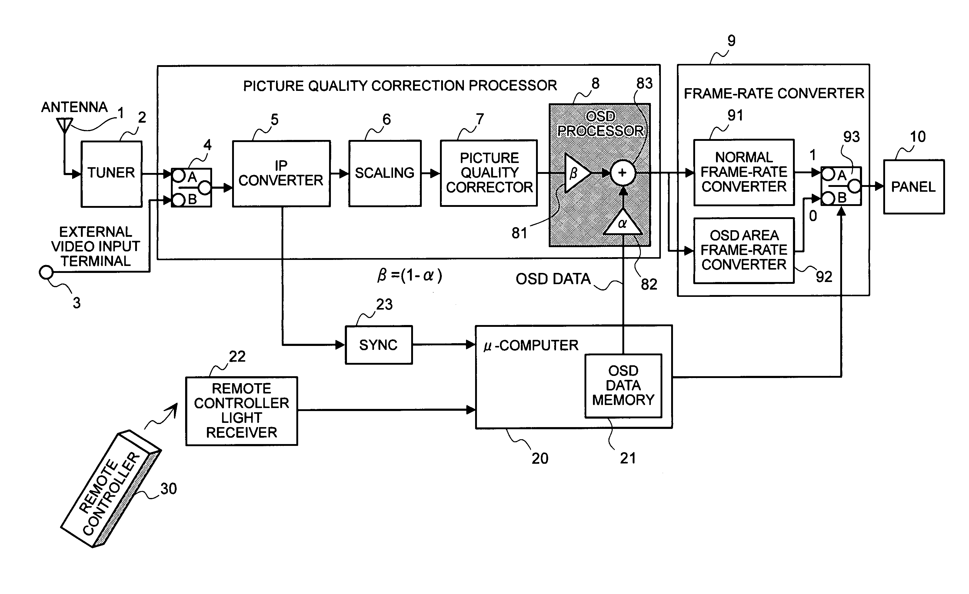
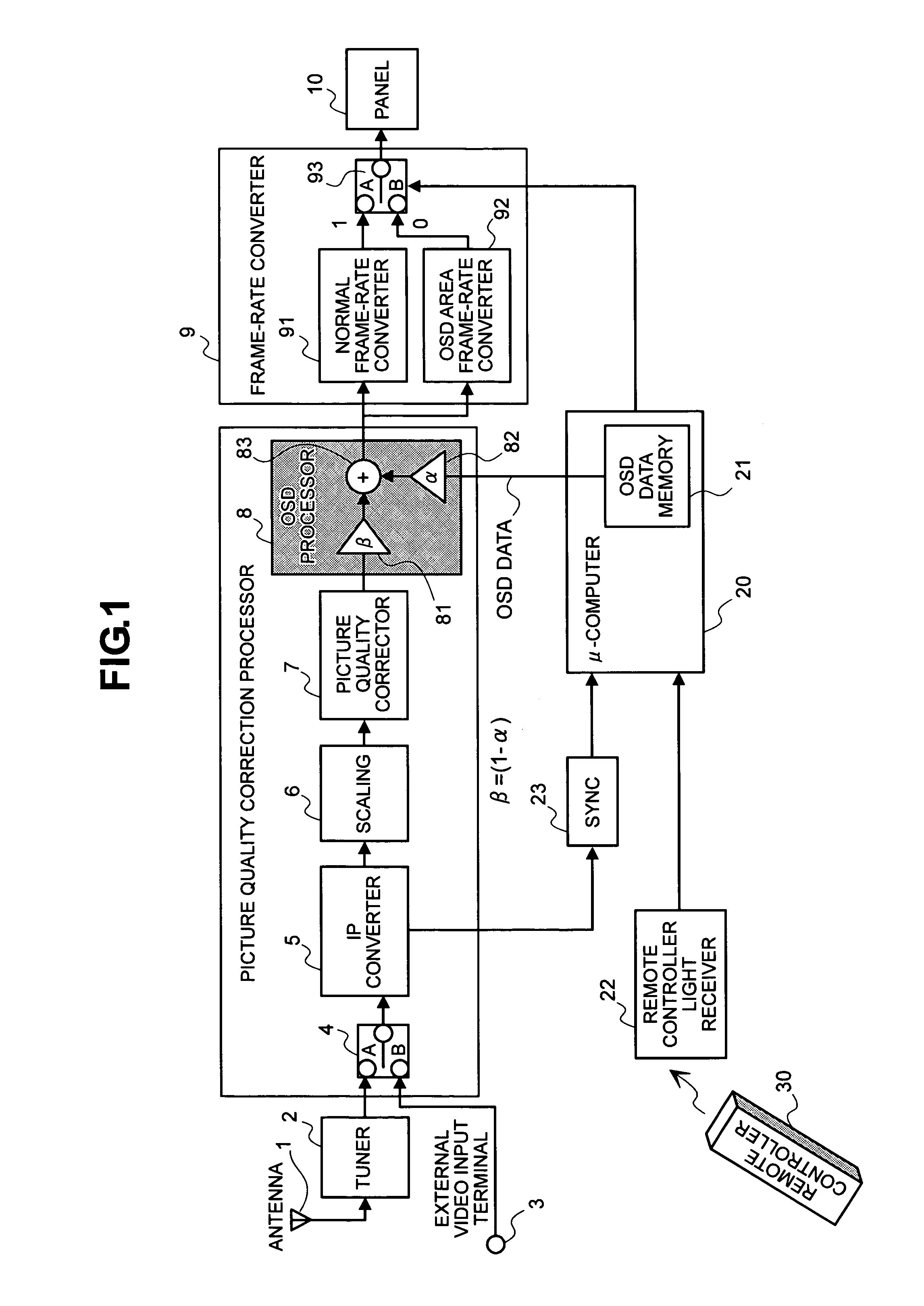
[0022]First of all, FIG. 1 attached herewith is a block diagram for showing the entire structures of a television receiver apparatus, according to an embodiment of the present invention.

[0023]In this FIG. 1, a broadcast video signal, such as, a digital broadcast signal, etc., for example, is received by an antenna 1, and it is inputted into an exchanger unit 4 through a tuner 2. On the other hand, into this exchanger unit 4 is further inputted a video signal from an external equipment, such as, a distribution information, etc., through an external video input terminal 3; i.e., within this exchanger unit 4, either the broadcast video signal supplied from the antenna 1 or the video signal supplied from the external video input terminal 3 is selected. However, herein, explanation will be made upon assumption that the broadcast video signal received by the ante...


PUM


Abstract

For providing television receiver apparatus and a video displaying method for that, i.e., suppressing deterioration of picture quality when conducting a frame-rate conversion on a video signal while piling up an OSD picture thereon, within the television receiver apparatus, picture quality correction is made on an input video signal including the moving picture therein. After inserting the OSD picture within an OSD inserter (OSD processor) unit 8, a frame-rate conversion is conducted within a frame-rate converter unit 9. Further, the frame-rate converter unit executes a frame-rate conversion accompanying a moving picture frame interpolation therewith, upon the video signal including the moving picture therein within a screen of one (1) frame to be displayed, while it executes a frame-rate conversion accompanying no moving picture frame interpolation therewith, upon the OSD picture, and thereby displaying the video signal including the moving picture therein on a display panel 10, together with the OSD picture, while conducting frame interpolation thereupon.

Description

BACKGROUND OF THE INVENTION[0001]The present invention relates to a video displaying technology for a television receiver, and it also relates, in particular, to a television receiver apparatus and a video displaying method for the same, for the purpose of preventing pictures from being deteriorated in the quality thereof, in case when displaying a stationary or still picture, such as, letters or characters, for example, lying or piling them on a moving picture.[0002]Conventionally, within a television receiver apparatus for enabling to receive digital broadcasts or the like, for example, with aiming an improvement in the picture quality thereof, it is already known to conduct a frame-rate conversion upon a video signal, with using a motion vector (i.e., increasing the number of frames), and thereby to achieve a video display as the moving picture with smooth changes, through conducting a frame interpolation thereon.[0003]For example, in the following Patent Document 1, as the conve...

Claims


Application Information

Patent Timeline
IPC IPC(8): H04N7/24H04N5/44H04N5/445H04N5/66H04N7/01H04N7/173
CPCH04N5/4403H04N5/44543H04N7/0127H04N7/0135H04N21/8153H04N21/431H04N21/440281H04N21/47H04N7/014H04N21/42204
Inventor KIMURA, KATSUNOBU
Owner HITACHI LTD
Why Eureka
Try Eureka