Sub-diffraction limit image resolution and other imaging techniques
What is Al technical title?
Al technical title is built by PatSnap Al team. It summarizes the technical point description of the patent document.
a sub-diffraction limit and image resolution technology, applied in the direction of instruments, material analysis through optical means, optical elements, etc., can solve the problems of microscopy using electrons, unsatisfactory limitations, and inconvenient use of fluorescence microscopy standard fluorescence microscopy
Inactive Publication Date: 2008-07-31
PRESIDENT & FELLOWS OF HARVARD COLLEGE
View PDF3 Cites 128 Cited by
Summary
Abstract
Description
Claims
Application Information
AI Technical Summary
This helps you quickly interpret patents by identifying the three key elements:
Problems solved by technology
Method used
Benefits of technology
Problems solved by technology
Despite these advantages, standard fluorescence microscopy is not useful for ultra-structural imaging, due to a resolution limit set by the diffraction of light.
Several approaches have been employed to try to pass this diffraction limit, including near-field scanning optical microscopy (NSOM), multi-photon fluorescence, stimulated emission depletion (STED), reversible saturable optical linear fluorescence transition (RESOLFT), and saturated structured-illumination microscopy (SSIM), but each has certain unsatisfactory limitations.
Electron microscopy is often used for high resolution imaging of biological samples, but microscopy uses electrons, rather than light, and is difficult to use with biological samples due to its preparation requirements.
Method used
Image
Click on the blue label to locate the original text in one second.
Reading with bidirectional positioning of images and text.
Examples
examples
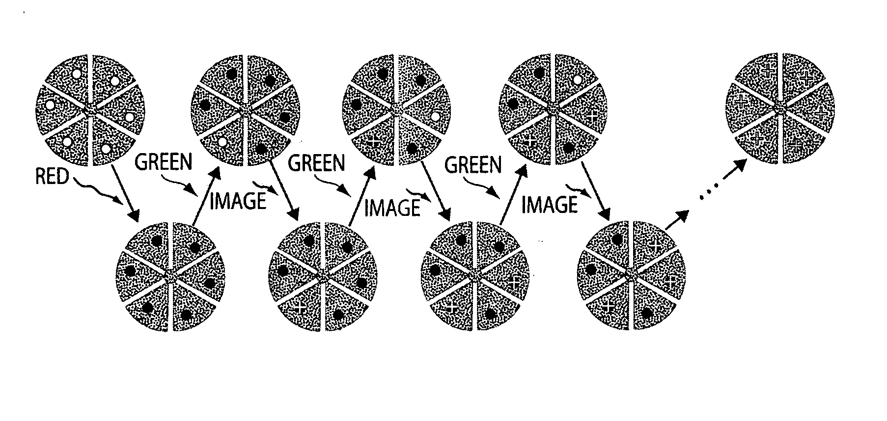
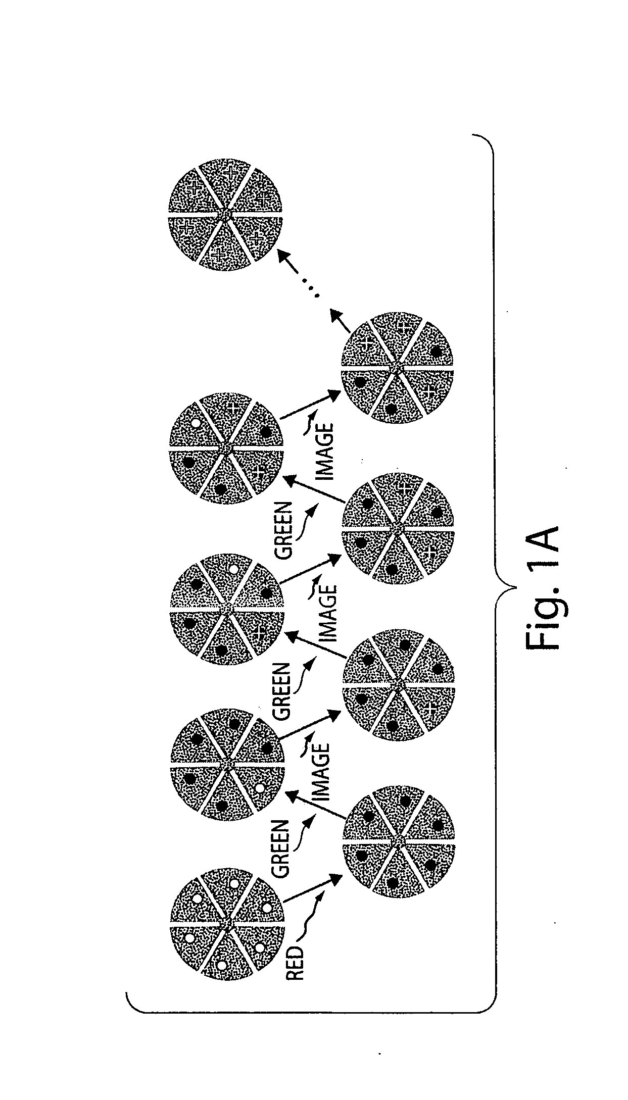
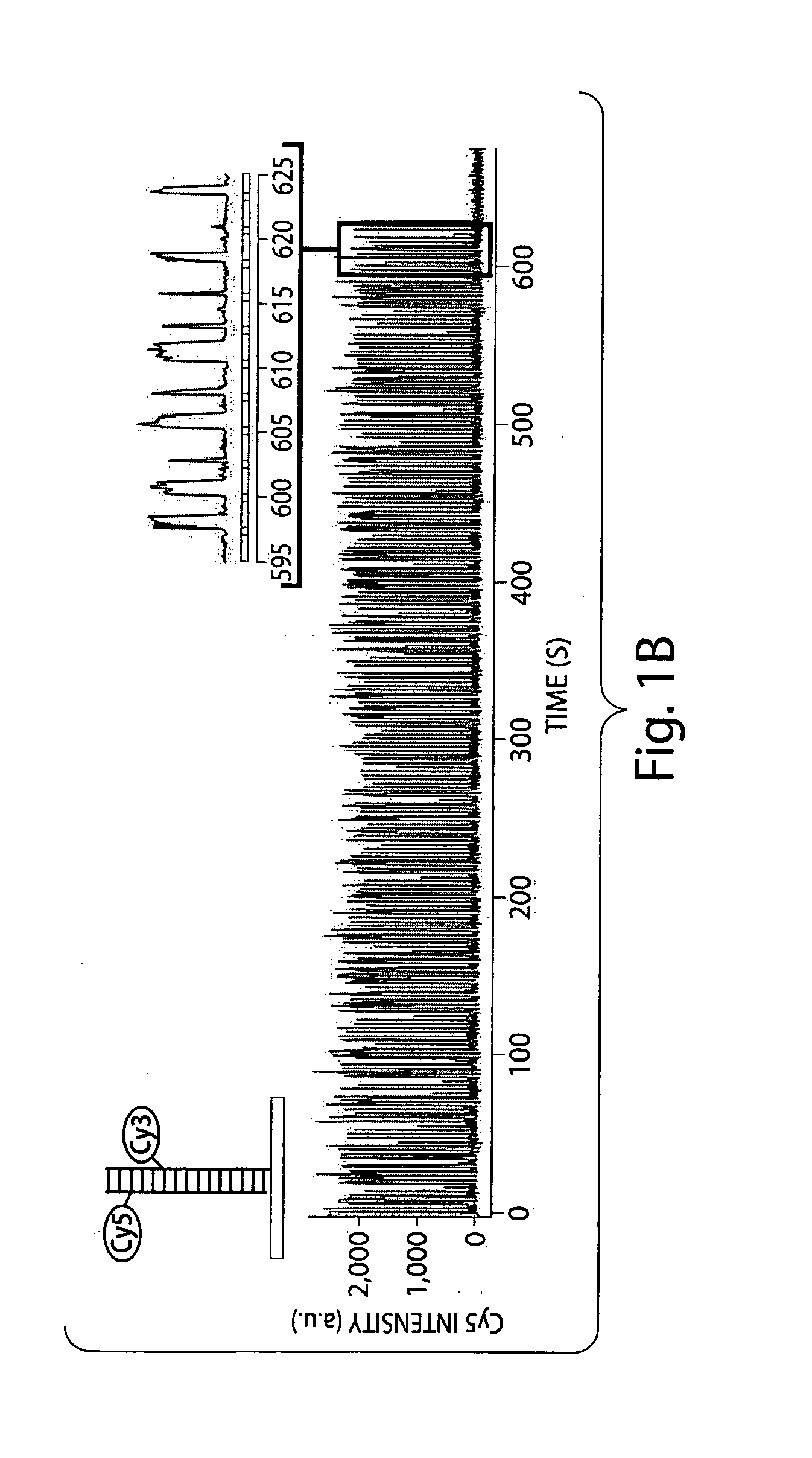
[0078]This example shows a high-resolution optical microscopy, stochastic optical reconstruction microscopy (“STORM”), in which a fluorescence image is constructed from high-accuracy localization of individual fluorescent entities (“fluorophores”) that are switched on and off using light of different colors, in accordance with one embodiment of the invention. The STORM imaging process in this example includes a series of imaging cycles (FIG. 1A). In each cycle, a fraction of the fluorophores in the field of view are switched on or activated, such that each of the active fluorophores is s optically resolvable from the rest, i.e. their images are not overlapping. This allows the position of these fluorophores to be determined with high accuracy. Repeating this process for multiple cycles, each causing a stochastically different subset of fluorophores to be turned on or activated, enables the positions of many fluorophores to be determined and thus an overall image to be reconstructed....
PUM
Property
Measurement
Unit
distance
aaaaa
aaaaa
distance
aaaaa
aaaaa
distance
aaaaa
aaaaa
Abstract
The present invention generally relates to sub-diffraction limit image resolution and other imaging techniques. In one aspect, the invention is directed to determining and / or imaging light from two or more entities separated by a distance less than the diffraction limit of the incident light. For example, the entities may be separated by a distance of less than about 1000 nm, or less than about 300 nm for visible light. In one set of embodiments, the entities may be selectively activatable, i.e., one entity can be activated to produce light, without activating other entities. A first entity may be activated and determined (e.g., by determining light emitted by the entity), then a second entity may be activated and determined. The entities may be immobilized relative to each other and / or to a common entity. The emitted light may be used to determine the positions of the first and second entities, for example, using Gaussian fitting or other mathematical techniques, and in some cases, with sub-diffraction limit resolution. The methods may thus be used, for example, to determine the locations of two or more entities immobilized relative to a common entity, for example, a surface, or a biological entity such as DNA, a protein, a cell, a tissue, etc. The entities may also be determined with respect to time, for example, to determine a time-varying reaction. Other aspects of the invention relate to systems for sub-diffraction limit image resolution, computer programs and techniques for sub-diffraction limit image resolution, methods for promoting sub-diffraction limit image resolution, methods for producing photoswitchable entities, and the like.
Description
RELATED APPLICATIONS[0001]This application claims priority to all of the following according to the following recitation of priority relationships. This application is a continuation-in-part of International Patent Application No. PCT / US2007 / 017618, filed Aug. 7, 2007, entitled “Sub-Diffraction Limit Image Resolution and other Imaging Techniques,” which claims priority to U.S. patent application Ser. No. 11 / 605,842, filed Nov. 29, 2006, entitled “Sub-Diffraction Image Resolution and other Imaging Techniques,” which claims the benefit of U.S. Provisional Patent Application Ser. No. 60 / 836,167, filed Aug. 7, 2006, entitled “Sub-Diffraction Image Resolution,” and the benefit of U.S. Provisional Patent Application Ser. No. 60 / 836,170, filed Aug. 8, 2006, entitled “Sub-Diffraction Image Resolution.” This application is also a continuation-in-part of said Ser. No. 11 / 605,842, which claims the benefit of said Ser. Nos. 60 / 836,167 and 60 / 836,170. Each of the above is incorporated herein by ...
Claims
Application Information
Patent Timeline
Application Date:The date an application was filed.
Publication Date:The date a patent or application was officially published.
First Publication Date:The earliest publication date of a patent with the same application number.
Issue Date:Publication date of the patent grant document.
PCT Entry Date:The Entry date of PCT National Phase.
Estimated Expiry Date:The statutory expiry date of a patent right according to the Patent Law, and it is the longest term of protection that the patent right can achieve without the termination of the patent right due to other reasons(Term extension factor has been taken into account ).
Invalid Date:Actual expiry date is based on effective date or publication date of legal transaction data of invalid patent.
Patent Type & Authority Applications(United States)