Continuous field tomography

a tomography and continuous field technology, applied in the field of tomography continuous field, can solve the problems of insufficient heart function, deterioration of cardiac function, and symptom development, and achieve the effect of facilitating the motion measurement of sensing elements and easy propagation through the tissu

Inactive Publication Date: 2008-07-31
PROTEUS DIGITAL HEALTH INC
View PDF54 Cites 114 Cited by
  • Summary
  • Abstract
  • Description
  • Claims
  • Application Information

AI Technical Summary

Benefits of technology

[0018]A pressure field based on acoustic wave can also facilitate measurement of an sensing element's motion. An ultrasonic wave is directed to a tissue region. The ultrasonic wave can easily propagate through the tissue. A moving sensing element within the tissue may receive the ultrasonic wave with a Doppler frequency shift. As a result, by measuring the amount of Doppler frequency shift, the direction and velocity of the electrode's movement can be determined.

Problems solved by technology

When congestive heart failure occurs, symptoms develop due to the heart's inability to function sufficiently.
Congestive heart failure is characterized by gradual decline in cardiac function punctuated by severe exacerbations leading eventually to death.
In the remaining third of patients, there is no improvement or, in a small minority, a deterioration in cardiac performance.
However, the current placement technique for CRT devices is usually empiric.
With the currently available techniques, rarely is there time or means for optimizing cardiac performance.
Current use of Doppler to localize elements in the heart have been limited to wall position determination via external ultrasonography, typically for purposes of measuring valve function, cardiac output, or rarely, synchronization index.
There is currently no useful clinically available means of determining optimal CRT settings on a substantially automatic or a real-time, machine readable basis.

Method used


Image

  • Continuous field tomography
  • Continuous field tomography
  • Continuous field tomography

Examples


Embodiment Construction

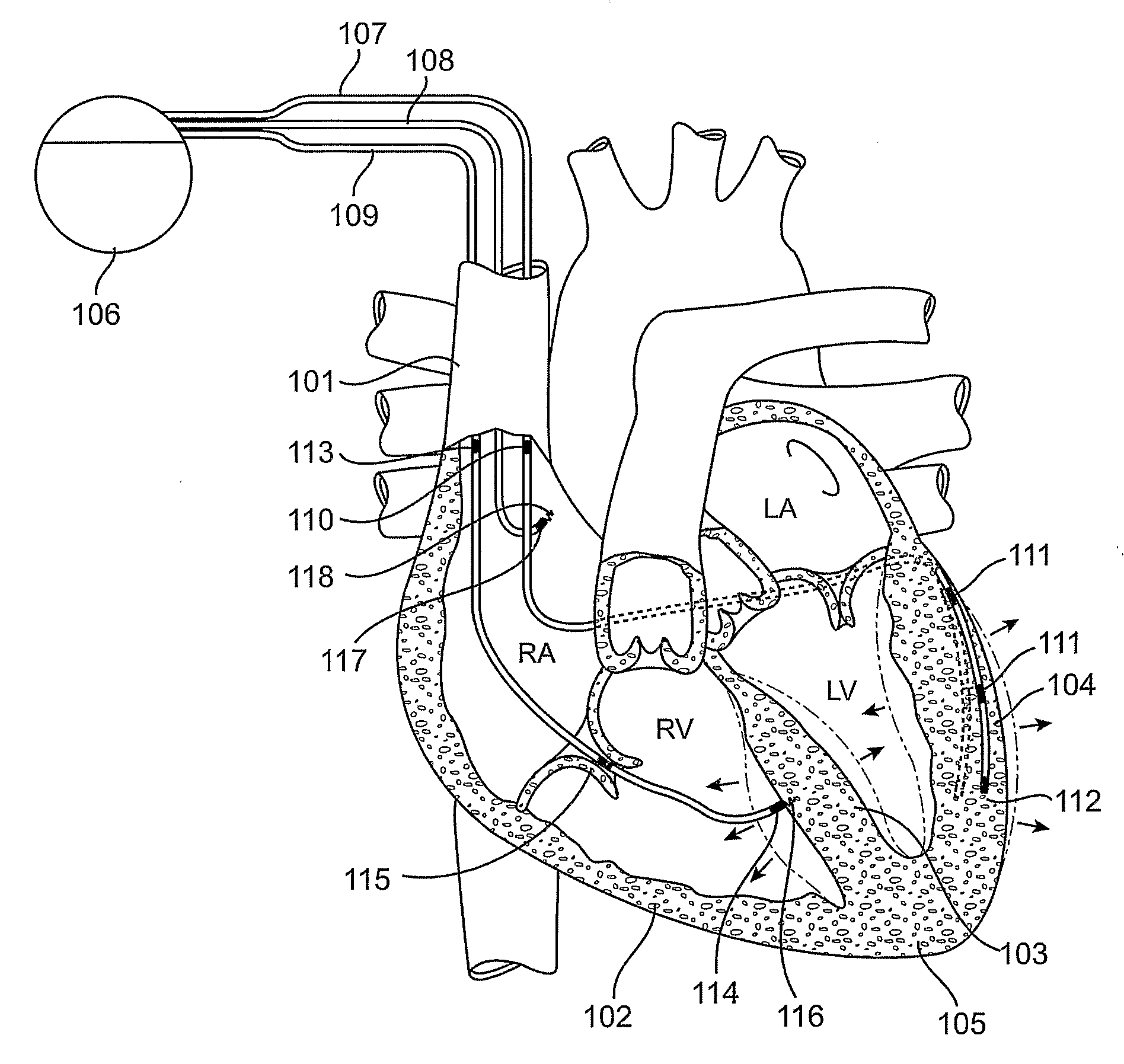
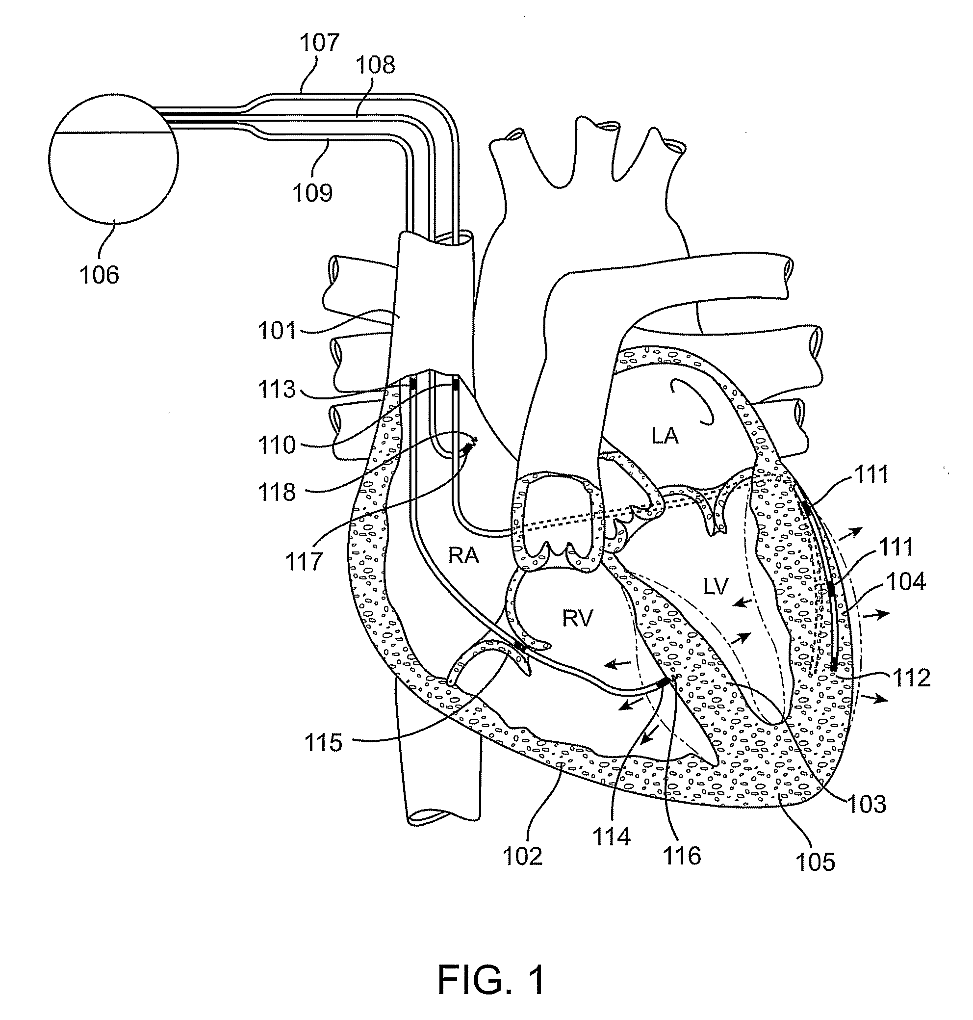
[0039]Methods for evaluating motion of a tissue location, such as of a cardiac location, e.g., a heart wall location, via continuous field tomography are provided. In the subject methods, a continuous field (e.g., an electrical field) sensing element is stably associated with the tissue location(s) of interest, and a property of the continuous field, e.g., a change in the continuous field, sensed by the sensing element is employed to evaluate movement of the tissue location. Also provided are systems, devices and related compositions for practicing the subject methods. The subject methods and devices find use in a variety of different applications, e.g., cardiac resynchronization therapy.

[0040]Before the present invention is described in greater detail, it is to be understood that this invention is not limited to particular embodiments described, as such may, of course, vary. It is also to be understood that the terminology used herein is for the purpose of describing particular emb...


PUM


Abstract

Methods for evaluating motion of a tissue, such as of a cardiac location, e.g., heart wall, via continuous field tomography are provided. In the subject methods, a continuous field (e.g., an electrical, mechanical, electro-mechanical, or other field) sensing element is stably associated with the tissue location. A property of the applied continuous field is detected with the sensing element to evaluate movement of the tissue location. Also provided are systems, devices and related compositions for practicing the subject methods. The subject methods and devices find use in a variety of different applications, including cardiac resynchronization therapy.

Description

CROSS-REFERENCE TO RELATED APPLICATIONS[0001]Pursuant to 35 U.S.C. § 119 (e), this application claims priority to the filing date of: U.S. Provisional Patent Application Ser. No. 60 / 617,618 filed Oct. 8, 2004; U.S. Provisional Patent Application Ser. No. 60 / 665,145 filed Mar. 25, 2005; U.S. Provisional Patent Application Ser. No. 60 / 696,321 filed Jun. 30, 2005; and U.S. Provisional Patent Application Ser. No. 60 / 705,900 filed Aug. 5, 2005; the disclosures of which are herein incorporated by reference.INTRODUCTIONBackground of the Invention[0002]In a diverse array of applications, the evaluation of tissue motion is desirable, e.g., for diagnostic or therapeutic purposes. An example of where evaluation of tissue motion is desirable is cardiac resynchronization therapy (CRT), where evaluation of cardiac tissue motion as observed by traditional ultrasound techniques is employed for diagnostic and therapeutic purposes.[0003]CRT is an important new medical intervention for patients suffer...

Claims


Application Information

Patent Timeline
Patent Type & Authority Applications(United States)
IPC IPC(8): A61B5/05
CPCA61B5/0031A61B5/1107A61B8/12A61B8/488A61B8/56A61N1/365A61B5/686A61B2562/046A61N1/3627
Inventor ROBERTSON, TIMOTHY L.SAVAGE, GEORGE M.THOMPSON, TODDZDEBLICK, MARK J.COLLIOU, OLIVIERCOSTELLO, BENEDICT J.
Owner PROTEUS DIGITAL HEALTH INC
Why Eureka
Try Eureka