Fibrosis-limiting material attachment

a technology of fibrosis-limiting materials and fibrosis-limiting materials, applied in electrotherapy, therapy, etc., can solve the problems of affecting the ability of fibrosis-limiting materials to be applied to shock coil electrodes in ways that lack sufficient attachment strength, and reducing the possibility of movement. , to achieve the effect of facilitating lead implantation and extractability, reducing the likelihood of movement, and improving the ease of chronic lead extraction

Inactive Publication Date: 2008-07-31
CARDIAC PACEMAKERS INC
View PDF30 Cites 20 Cited by
  • Summary
  • Abstract
  • Description
  • Claims
  • Application Information

AI Technical Summary

Benefits of technology

[0008]Advantageously, the present leads and methods decrease the likelihood of moving or shifting between a shocking coil electrode and a fibrosis-limiting material covering thereon or between the shocking coil electrode and adjacent portions of a lead body, such as during the lead implantation process. In this way, there is a reduction or elimination of uncovered, implanted shocking coil electrodes that are subject to future fibrotic entanglement, thereby improving the ease of chronic lead extraction should it become necessary. Additionally, the present leads and methods provide smooth transitions at the lead body-shocking coil electrode interface, which also facilitate lead implantation and extractability. These and other examples, advantages, and features of the present leads and methods will be set forth in part in the detailed description, which follows, and in part will become apparent to those skilled in the art by reference to the following description of the present leads, methods, and drawings or by practice of the same.

Problems solved by technology

Once implanted, the exposed shocking coil electrodes often become entangled with fibrosis (i.e., a capsule of inactive tissue which grows into the exposed coils) with the end result being that a chronically implanted lead can be extremely difficult to remove by the application of tensile force to the lead proximal end.
Over time, situations may arise which require the removal and replacement of an implanted defibrillator lead.
Unfortunately, current fibrosis-limiting materials are applied to the shocking coil electrodes in ways that lack sufficient attachment strength.
As a result, when subjected to shear loads, such as during lead implantation procedures, the fibrosis-limiting material may separate from the associated shocking coil electrode or the shocking coil electrodes themselves may separate from the lead body or deform, thereby leaving uncovered coils that are subject to future fibrotic entanglement.
Advantageously, the present leads and methods decrease the likelihood of moving or shifting between a shocking coil electrode and a fibrosis-limiting material covering thereon or between the shocking coil electrode and adjacent portions of a lead body, such as during the lead implantation process.
Unfortunately, the nature of fibrosis-limiting materials and previous manufacturing methods to attach such materials to the shocking coil electrodes lack in physical strength.
As one example, certain fibrosis-limiting materials, such as expanded polytetrafluoroethylene (ePTFE), resist adhesion due to their chemical nature and require extremely high heat to sinter to a shocking coil electrode.
This high heat exceeds temperatures that many lead body materials can withstand.
It has been found that when implanting such previously manufactured defibrillator leads, high drag forces are created along the lead body (e.g., due to an introducer seal of a hemostatic introducer).
As a result, several lead component interfaces, including the fibrosis-limiting material to shocking coil electrode and the shocking coil electrode to lead body, have a tendency to separate or shift relative to one another leaving one or more uncovered coils.

Method used


Image

  • Fibrosis-limiting material attachment
  • Fibrosis-limiting material attachment
  • Fibrosis-limiting material attachment

Examples


Embodiment Construction

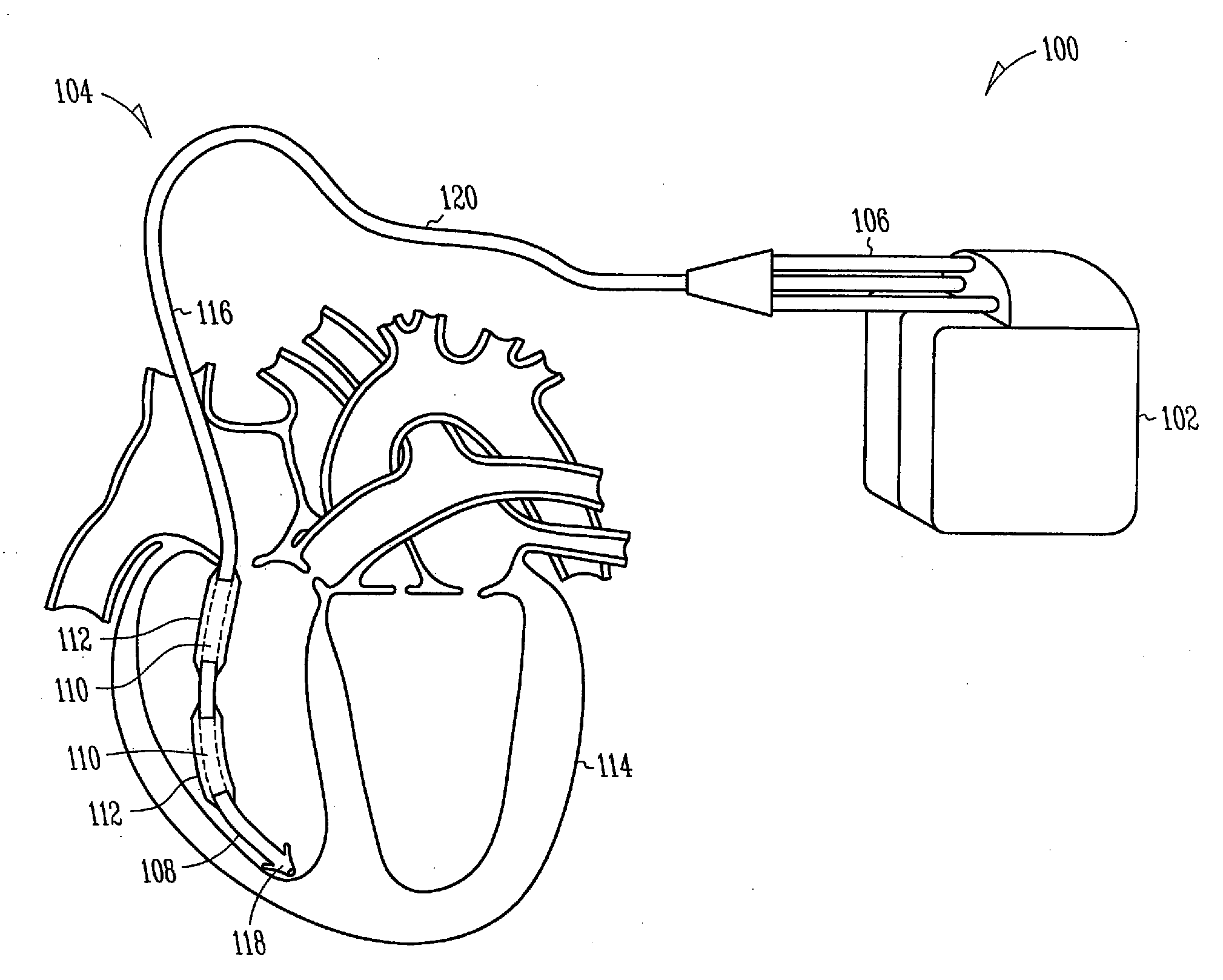
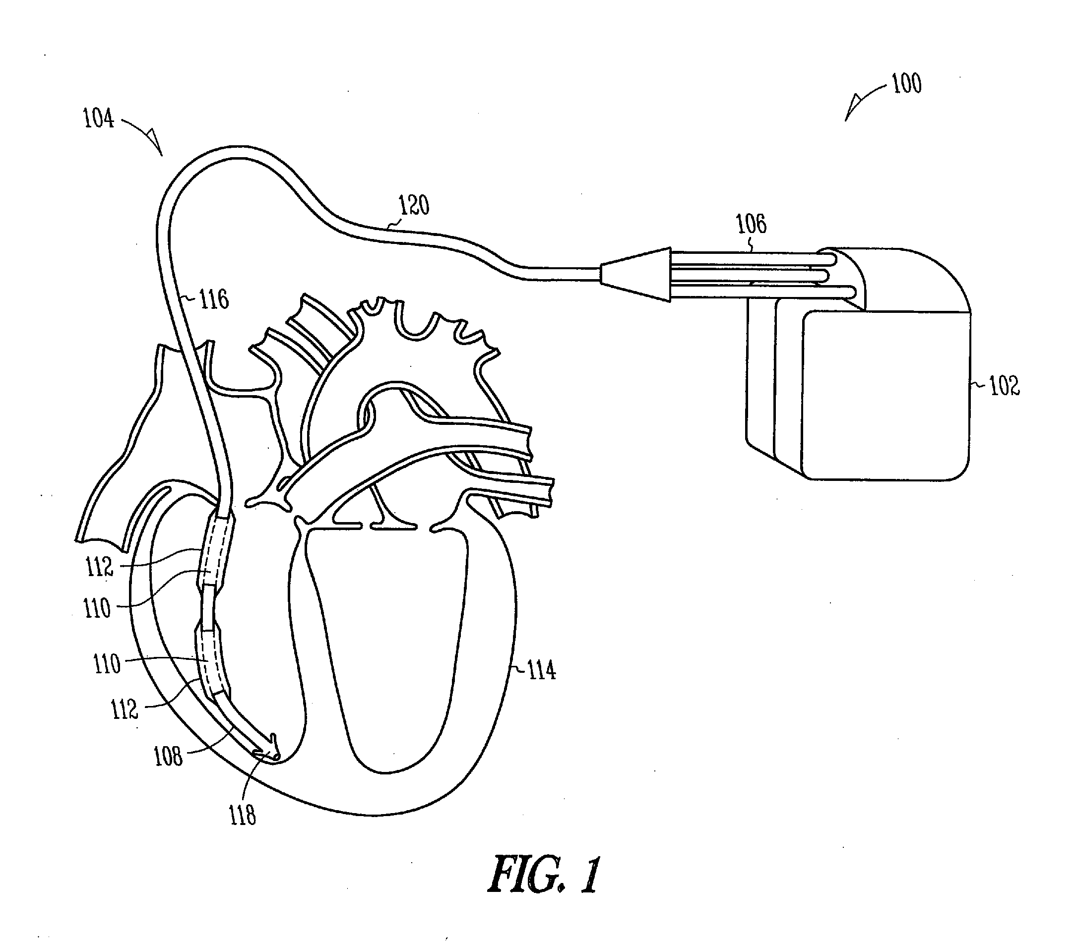
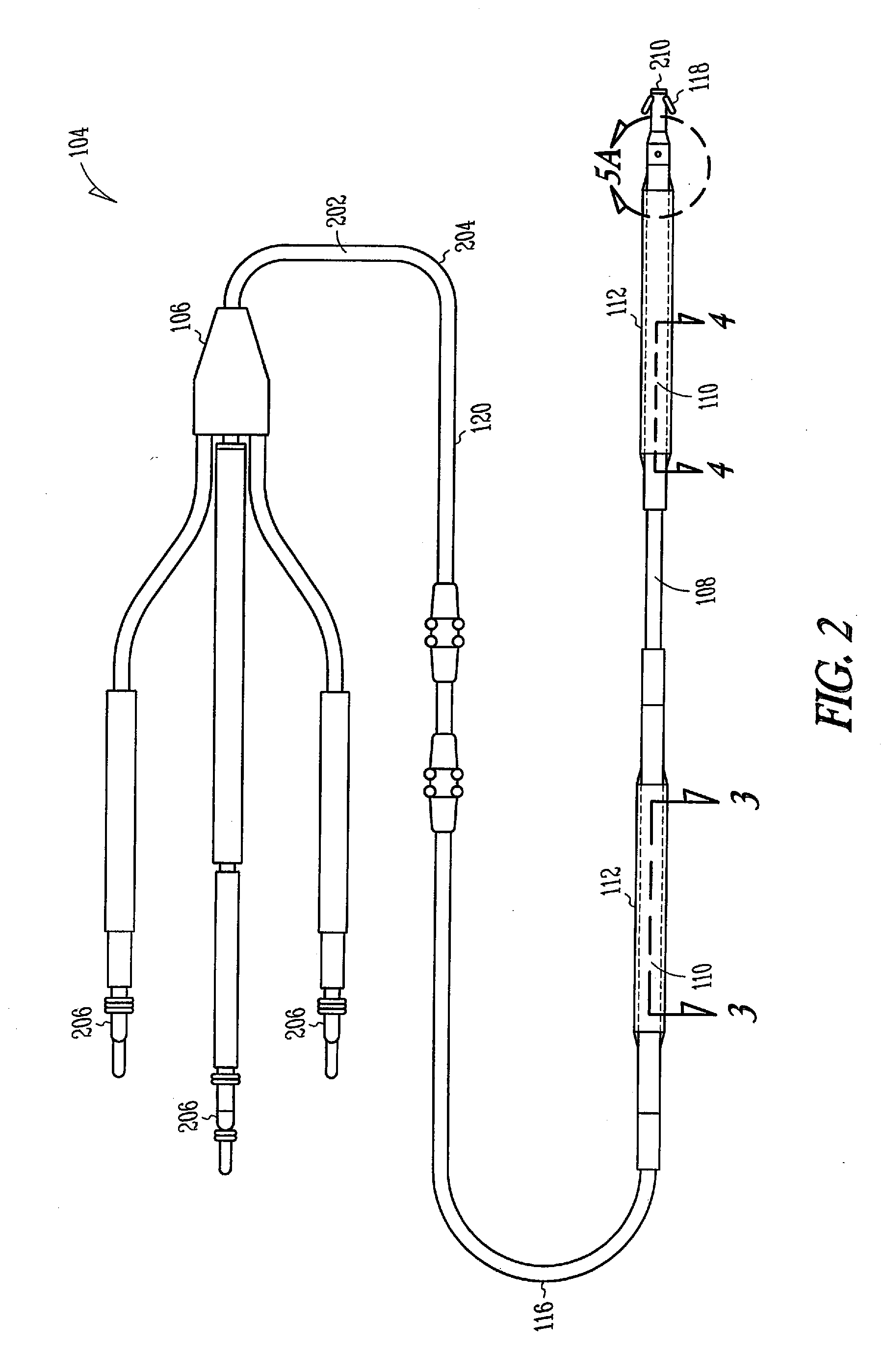
[0019]The following detailed description includes references to the accompanying drawings, which form a part of the detailed description. The drawings show, by way of illustration, specific embodiments in which the present leads and methods may be practiced. These embodiments, which are also referred to herein as “examples,” are described in enough detail to enable those skilled in the art to practice the present leads and methods. The embodiments may be combined, other embodiments may be utilized or structural or logical changes may be made without departing from the scope of the present leads and methods. The following detailed description is, therefore, not to be taken in a limiting sense, and the scope of the present leads and methods is defined by the appended claims and their legal equivalents.

[0020]In this document, the terms “a” or “an” are used to include one or more than one, and the term “or” is used to refer to a nonexclusive “or” unless otherwise indicated. In addition,...


PUM


Abstract

Defibrillator lead designs and methods for improved attachment strength between a fibrosis-limiting material covering, a shocking coil electrode, and an implantable lead body are disclosed herein. In certain examples, a portion of the fibrosis-limiting material extends proximal or distal to a shocking coil end and is disposed between a first and a second lead component. In certain examples, a length of compression tubing is utilized. A chronically implanted lead is often encapsulated by a body's fibrotic reaction, which in turn causes future lead explantation to be exceedingly difficult. To reduce fibrotic entanglement, the fibrosis-limiting material covering surrounds strategic portions of the lead. Improving the attachment between the fibrosis-limiting material covering, the shocking coil electrode, and the lead body will allow for improved performance, durability, and extractability of the lead. This disclosure describes several defibrillator lead designs and methods to create these improved joints.

Description

TECHNICAL FIELD[0001]This patent document pertains generally to implantable defibrillator leads. More particularly, but not by way of limitation, this patent document pertains to the attachment of fibrosis-limiting material to one or more portions of an implantable defibrillator lead.BACKGROUND[0002]Cardiac and other defibrillation systems typically include an implantable medical device (IMD), such as a pulse generator, electrically connected to the heart by at least one implantable defibrillator lead. More specifically, an implantable defibrillator lead provides an electrical pathway between the IMD, connected to a proximal end of the lead, and cardiac tissue, in contact with a distal end of the lead. In such a manner, electrical stimulation (e.g., in the form of one or more shocks or countershocks) emitted by the IMD may travel through the implantable defibrillator lead and stimulate the heart via one or more exposed, helically wound shocking coil electrodes located at or near the...

Claims


Application Information

Patent Timeline
Patent Type & Authority Applications(United States)
IPC IPC(8): A61N1/00
CPCA61N1/0563
Inventor HAMMILL, ERIC FALBEFANGMEIER, MICHELLEARNEBERG, JAMES P.
Owner CARDIAC PACEMAKERS INC
Why Eureka
Try Eureka