Error detection code generating circuit and encoding circuit utilizing which and method thereof

a technology of error detection code and generating circuit, which is applied in the direction of coding, recording signal processing, instruments, etc., can solve the problem of large bandwidth and achieve the effect of reducing the bandwidth needed for data reading

Active Publication Date: 2008-07-31
REALTEK SEMICON CORP
View PDF19 Cites 2 Cited by
  • Summary
  • Abstract
  • Description
  • Claims
  • Application Information

AI Technical Summary

Benefits of technology

[0007]Therefore, one objective of the present invention is to provide an EDC generating circuit, which can decrease the bandwidth needed for the EDC in the circumstance that the transmission interface and the header generator are independent.
[0008]Another objective of the present invention is to provide an encoding circuit, which can utilize minimum bandwidth for the EDC in the circumstance that the transmission interface and the header generator are independent.

Problems solved by technology

The disadvantage of such a system is that the scrambler must read and write back data of whole sector, and therefore, large bandwidth is needed.
Additionally, according to structure of the optical disc encoding system, the EDC generator needs to read a whole sector to generate only 4 bytes EDC, which is inefficient.

Method used


Image

  • Error detection code generating circuit and encoding circuit utilizing which and method thereof
  • Error detection code generating circuit and encoding circuit utilizing which and method thereof
  • Error detection code generating circuit and encoding circuit utilizing which and method thereof

Examples


first embodiment

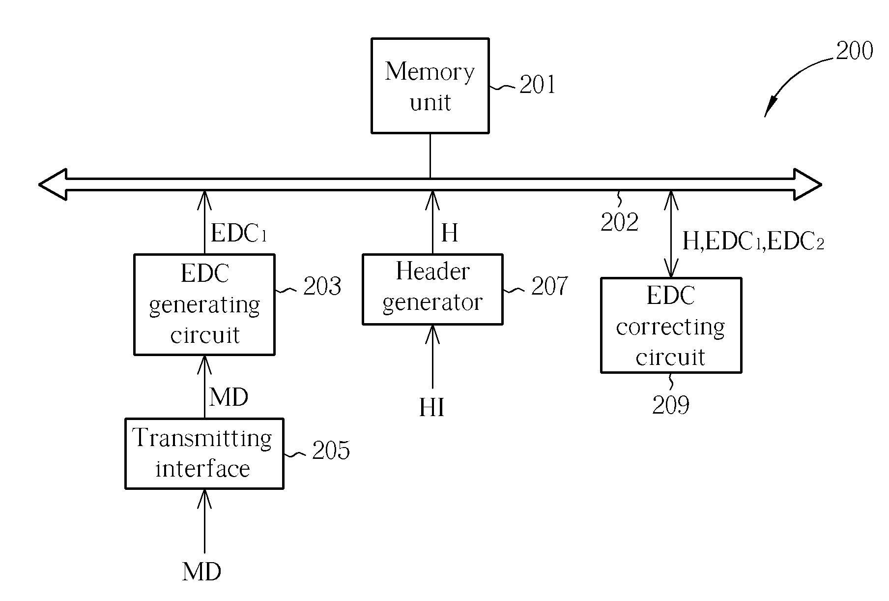
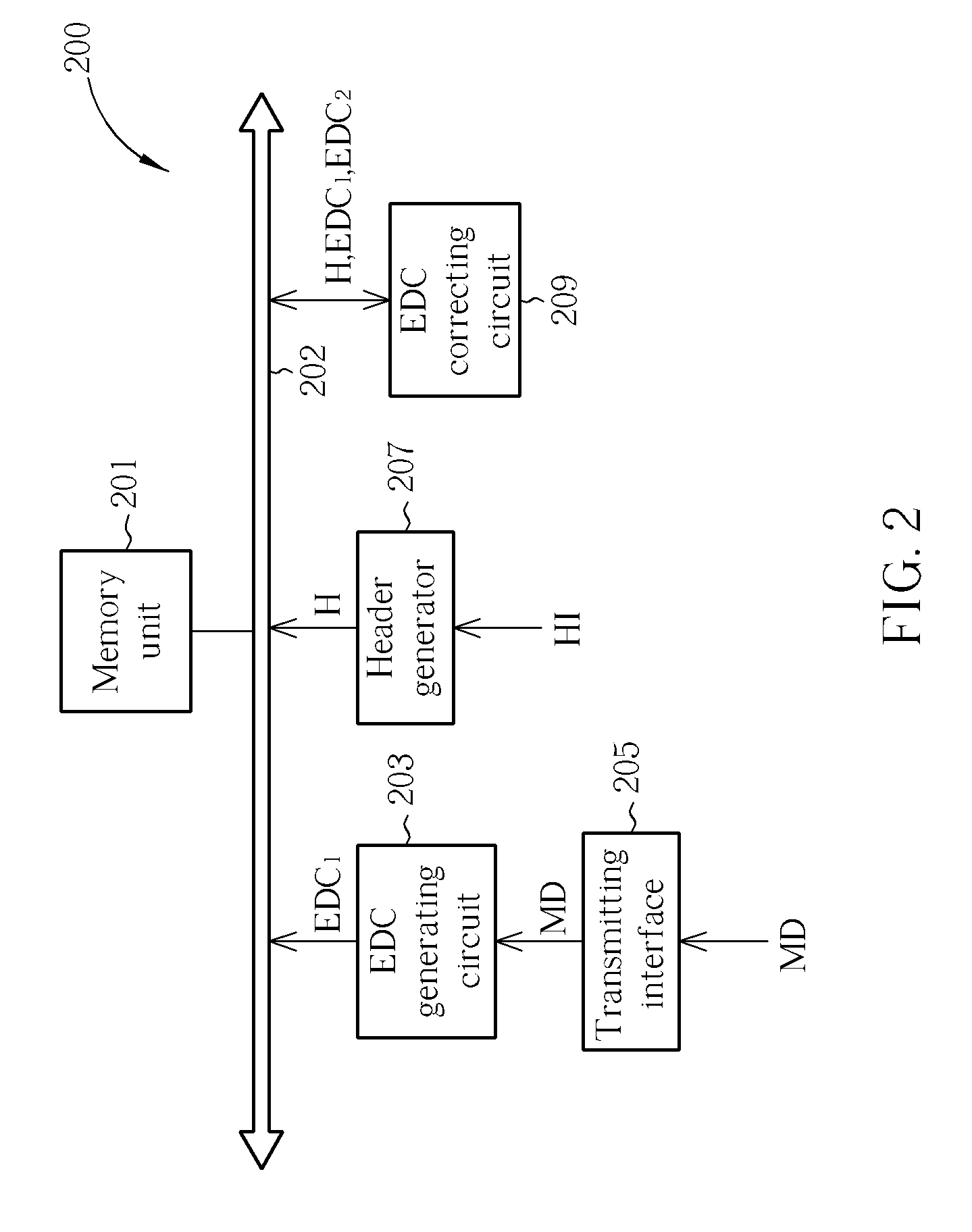
[0024]FIG. 2 is an optical disc data EDC generating circuit 200 according to the present invention. As shown in FIG. 2, the optical disc data EDC generating circuit 200 includes a memory unit 201, a bus 202, an EDC generating circuit 203, a transmitting interface 205, a header generator 207 and an EDC correcting circuit 209. The transmitting interface 205 is used for receiving main data MD. The EDC generating circuit 203, which is coupled to the memory unit 201 via the bus 202, is used for generating a first EDC (EDC1) according to at least one main data MD, and for storing EDC1 to the memory unit 201. The header generator 207, which is coupled to the memory unit 201, is used for generating a header H according to header information Hi. The EDC correcting circuit 209, which is coupled to the memory unit 201, is used for reading the EDC1 from the memory unit 201 and for correcting the EDC1 according to the header H to generate a second EDC (EDC2).

[0025]Besides above-mentioned operati...

second embodiment

[0029]FIG. 3 is an optical disc data EDC generating circuit 300 according to the present invention. The optical disc data EDC generating circuit 300 includes a memory unit 301, a bus 302, an EDC generating circuit 303, a transmitting interface 305, an EDC correcting circuit 307 and a header generator 309. The difference between the optical disc data EDC generating circuits 300 and 200 is that the header generator 309 of the optical disc data EDC generating circuit 300 is further coupled to the EDC correcting circuit 307, therefore the EDC correcting circuit 307 can directly receive the header H from the header generator 309, and amends the EDC1 according to the header H to generate EDC2. By this way, the computing and operation time of the header generator 309 can be shortened.

[0030]The operation of the optical disc data EDC generating circuits 200 and 300 can be integrated to the steps shown in FIG. 4. FIG. 4 is an optical disc EDC generating method according to an embodiment of th...

third embodiment

[0040]FIG. 7 is an optical data encoding system 700 according to the present invention. The optical data encoding system 700 includes the same elements as the optical data encoding systems 500 and 600, but has different connection types. As shown in FIG. 7, the EDC correcting circuit 701 is coupled to the encoder 703. Thus the EDC1 and the header H are stored in the memory unit 705 in this embodiment, then the EDC correcting circuit 701 reads the EDC1 and the header H from the memory unit 705, and amends the EDC1 according to the header H to generate the EDC2. The encoder 703 encodes according to scrambled main data DMD, header H and EDC2 to generate PI, PO. Please note that the EDC correcting circuit 701 finishes the operation of correcting EDC before the encoder 703 utilizes the EDC2 to perform PI / PO encoding.

[0041]FIG. 8 is an optical data encoding method according to a third embodiment of the present invention, which corresponds to the circuits shown in FIG. 5 to FIG. 7. The met...


PUM


Abstract

An EDC generating circuit includes a memory unit, an EDC generating circuit, a header generator and an EDC correcting circuit. The EDC generating circuit, which is coupled to the memory unit, is used for generating a first EDC according to at least one main data, and for storing the first EDC to the memory unit. The header generator, which is coupled to the memory unit, is used for generating a header according to header information. The EDC correcting circuit, which is coupled to the memory unit, is used for reading the first EDC from the memory unit and for correcting the first EDC according to the header to generate a second EDC.

Description

BACKGROUND OF THE INVENTION[0001]1. Field of the Invention[0002]The present invention relates to an error detection code generating circuit, an encoding circuit utilizing which and related methods thereof, and particularly relates to an optical data error detection code generating circuit, an encoding circuit utilizing which and related methods thereof.[0003]2. Description of the Prior Art[0004]Conventionally, a DVD optical disc comprises continuous error correction code block (ECC block), and a DVD optical disc includes at least 143500 ECC blocks, which is illustrated as conform tos. FIG. 1 is a schematic diagram illustrating the ECC block 100 in a DVD optical disc. As shown in FIG. 1, each ECC block has 208 (192+16) rows, and each of them has 182 bytes (172+10). The first 172 bytes of each row is used for storing data to be recorded to the optical disc, and the information stored in the last 10 bytes is the PI (Parity of the Inner code). Also, the last 16 rows of each ECC block ar...

Claims


Application Information

Patent Timeline
Patent Type & Authority Applications(United States)
IPC IPC(8): H03M13/00
CPCG11B20/1833H03M13/09G11B2220/2537
Inventor CHEN, CHIEN-CHIHKUO, SHIEH-HSING
Owner REALTEK SEMICON CORP
Why Eureka
Try Eureka