Resonator Measurement Device and Method Employing the Device

a technology of resonance measurement and measurement device, which is applied in the field of electroanautics, can solve problems such as degrading the vacuum within the chamber, and achieve the effect of improving the knowledge of the precision level of the pressure sensor

Active Publication Date: 2008-08-07
THALES SA
View PDF10 Cites 19 Cited by
  • Summary
  • Abstract
  • Description
  • Claims
  • Application Information

AI Technical Summary

Benefits of technology

[0008]One object of the invention is to improve the knowledge of the precision level of the pressure sensor during its use and to avoid having to...

Problems solved by technology

Several effects may degrade the vacuum within the chamber, such as in particular leaks that may occur at the joints of v...

Method used


Image

  • Resonator Measurement Device and Method Employing the Device
  • Resonator Measurement Device and Method Employing the Device
  • Resonator Measurement Device and Method Employing the Device

Examples


Embodiment Construction

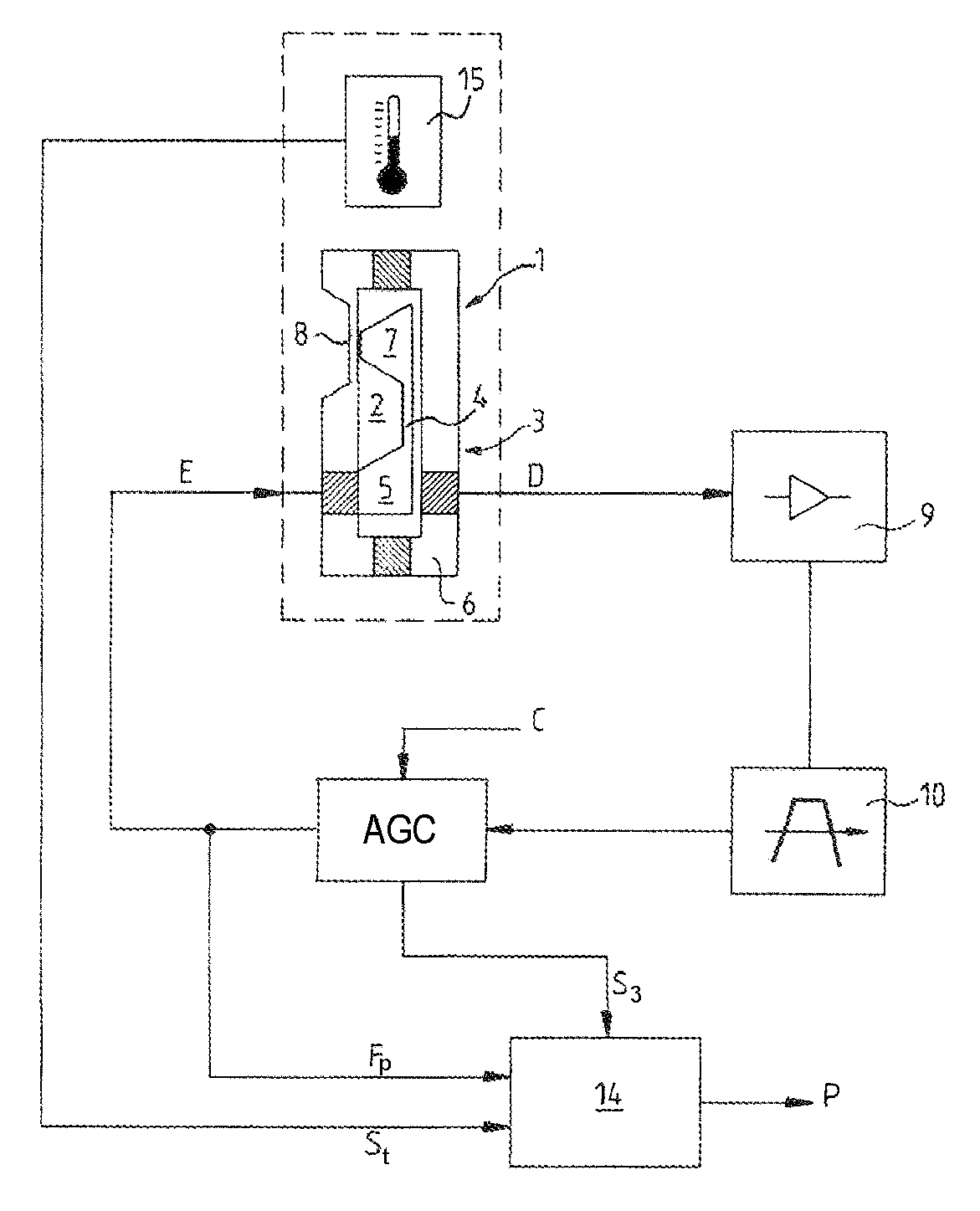
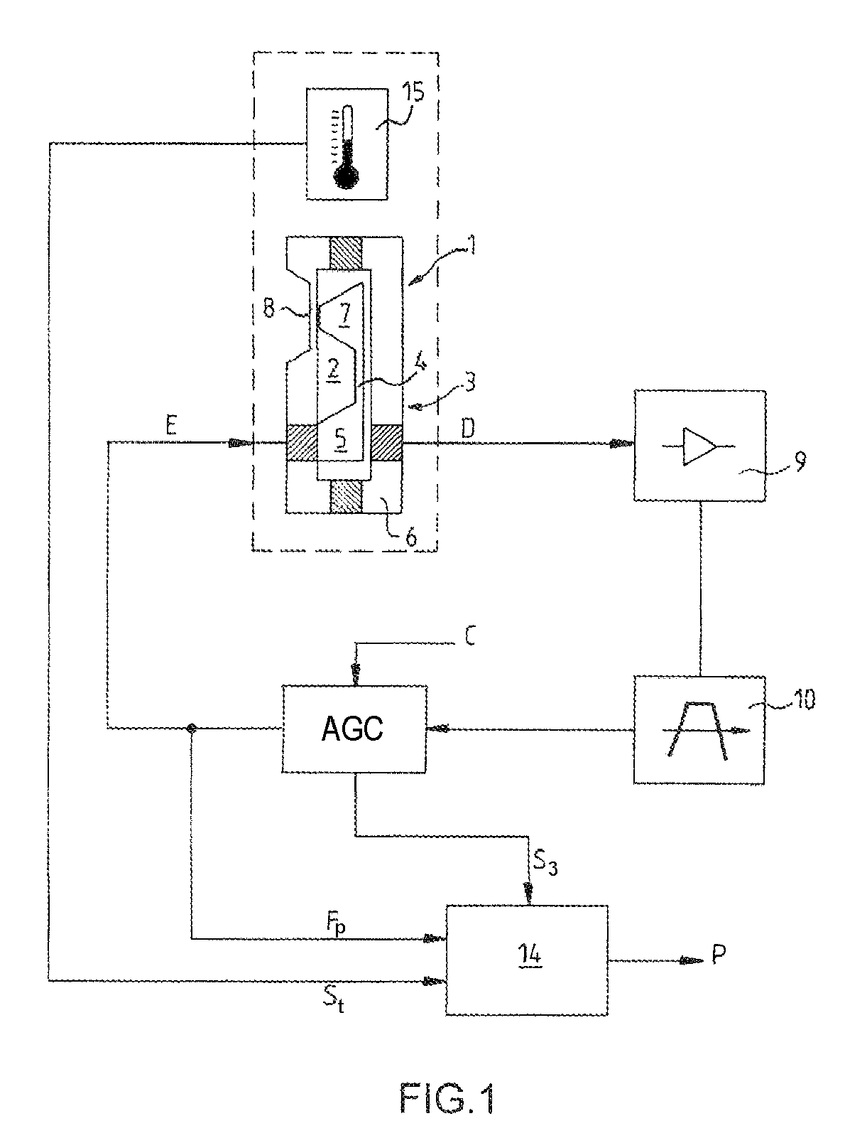
[0014]FIG. 1 shows an air pressure measurement device including a pressure sensor 1 and a chamber 2 maintained at a reference pressure, generally close to vacuum. The pressure sensor 1 measures a pressure difference between the chamber 2 and the air surrounding the pressure sensor 1.

[0015]Advantageously, the device comprises a resonator 3 and means for measuring a resonant frequency of the resonator 3. The resonator 3 is for example produced by means of a silicon plate 4 which can come into resonance under the effect of an electrical excitation signal E. The silicon plate 4 is located in the chamber 2. The silicon plate 4 is embedded at one of its ends, 5, in a body 6 of the resonator 3 and at the other of its ends, 7, on a thinned wall 8 of the chamber 2. The wall 8 is exposed on one of its faces to the pressure of the air, i.e. the pressure to be measured, and on the other of its faces to the pressure in the chamber 2. The wall 8 deforms according to the pressure difference betwee...


PUM


Abstract

The invention relates to a device and a method for detecting a fault in a measurement device comprising a resonator and means for measuring a resonant frequency of the resonator. According to the invention, the device further includes means delivering information (S3) representative of the quality factor of the resonator (3) at the resonant frequency.

Description

CROSS-REFERENCE TO RELATED APPLICATIONS[0001]The present Application is based on International Application No. PCT / EP2005 / 056961 filed on Dec. 20, 2005, which in turn corresponds to France Application No. 04 13965 filed on Dec. 27, 2004 and France Application No. 05 00591, filed on Jan. 20, 2005, and priority is hereby claimed under 35 USC §119 based on these applications. Each of these applications are hereby incorporated by reference in their entirety into the present application.FIELD OF THE INVENTION[0002]The present invention relates to the field of aeronautics, and more particularly, to a device and a method for detecting a fault in a measurement device comprising a resonator and means for measuring a resonant frequency of the resonator.BACKGROUND OF THE INVENTION[0003]The invention relates to a device and a method for detecting a fault in a measurement device comprising a resonator and means for measuring a resonant frequency of the resonator. The measurement device comprises...

Claims


Application Information

Patent Timeline
IPC IPC(8): G01L11/04G01N29/12G01K11/22G01P5/14G01L27/00
CPCG01L9/0008G01L9/0019G01L27/007G01N2291/02872G01N2291/02881G01L21/22
Inventor LEVERRIER, BERTRANDLEFORT, OLIVIER
Owner THALES SA
Why Eureka
Try Eureka