Stator support structure for a torque converter

Inactive Publication Date: 2008-08-07
TOYOTA JIDOSHA KK
View PDF5 Cites 8 Cited by
  • Summary
  • Abstract
  • Description
  • Claims
  • Application Information

AI Technical Summary

Benefits of technology

[0008]The present invention provides an inexpensive stator support device for a torque co

Problems solved by technology

It is relatively difficult to machine the keys provided on the stator, and because oil supplied from the oil passage groove of the outer race passes through the key groove, it is necessary to make t

Method used


Image

  • Stator support structure for a torque converter
  • Stator support structure for a torque converter
  • Stator support structure for a torque converter

Examples


Embodiment Construction

[0020]Example embodiments of the present invention are described below, with reference made to the accompanying drawings.

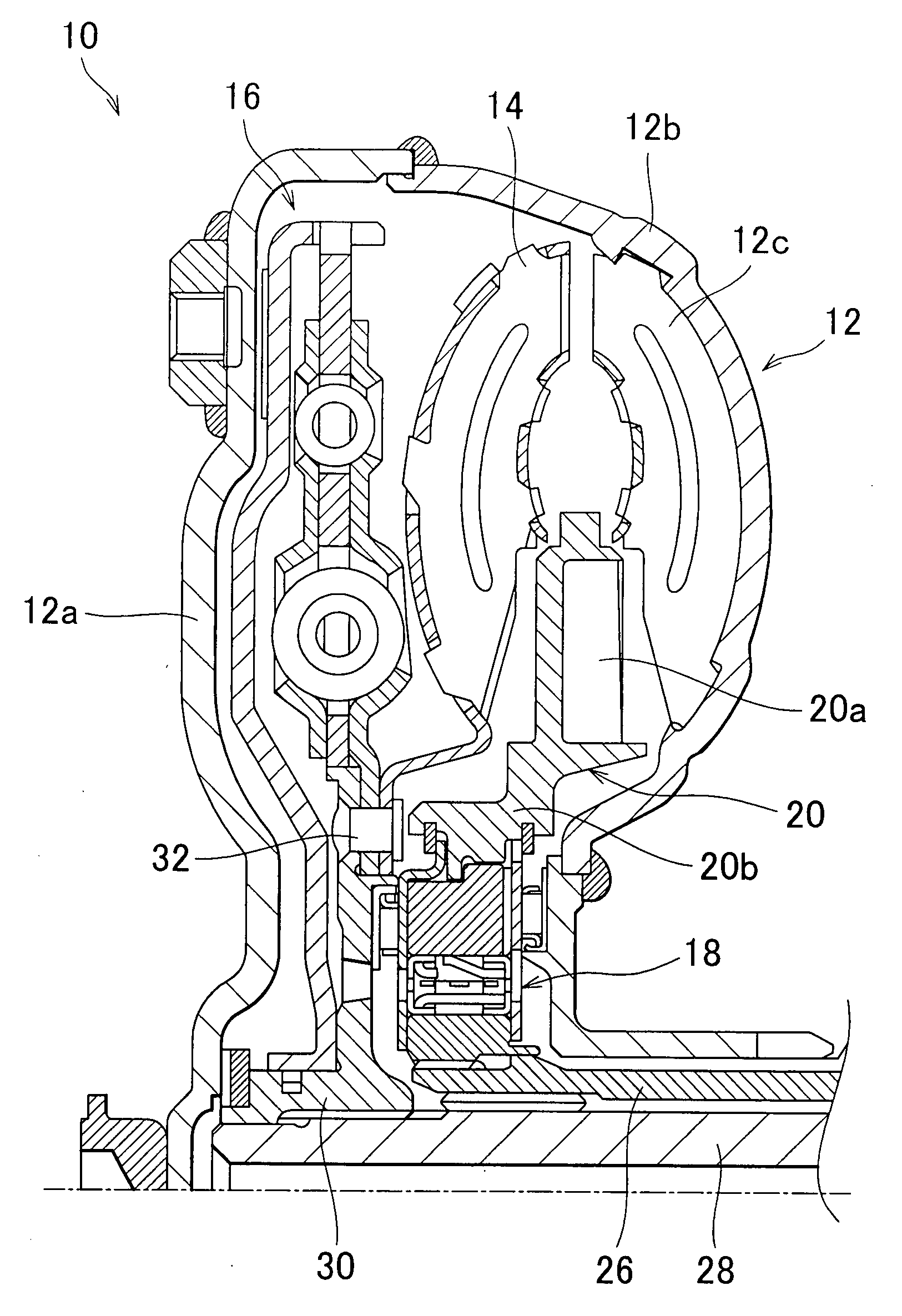
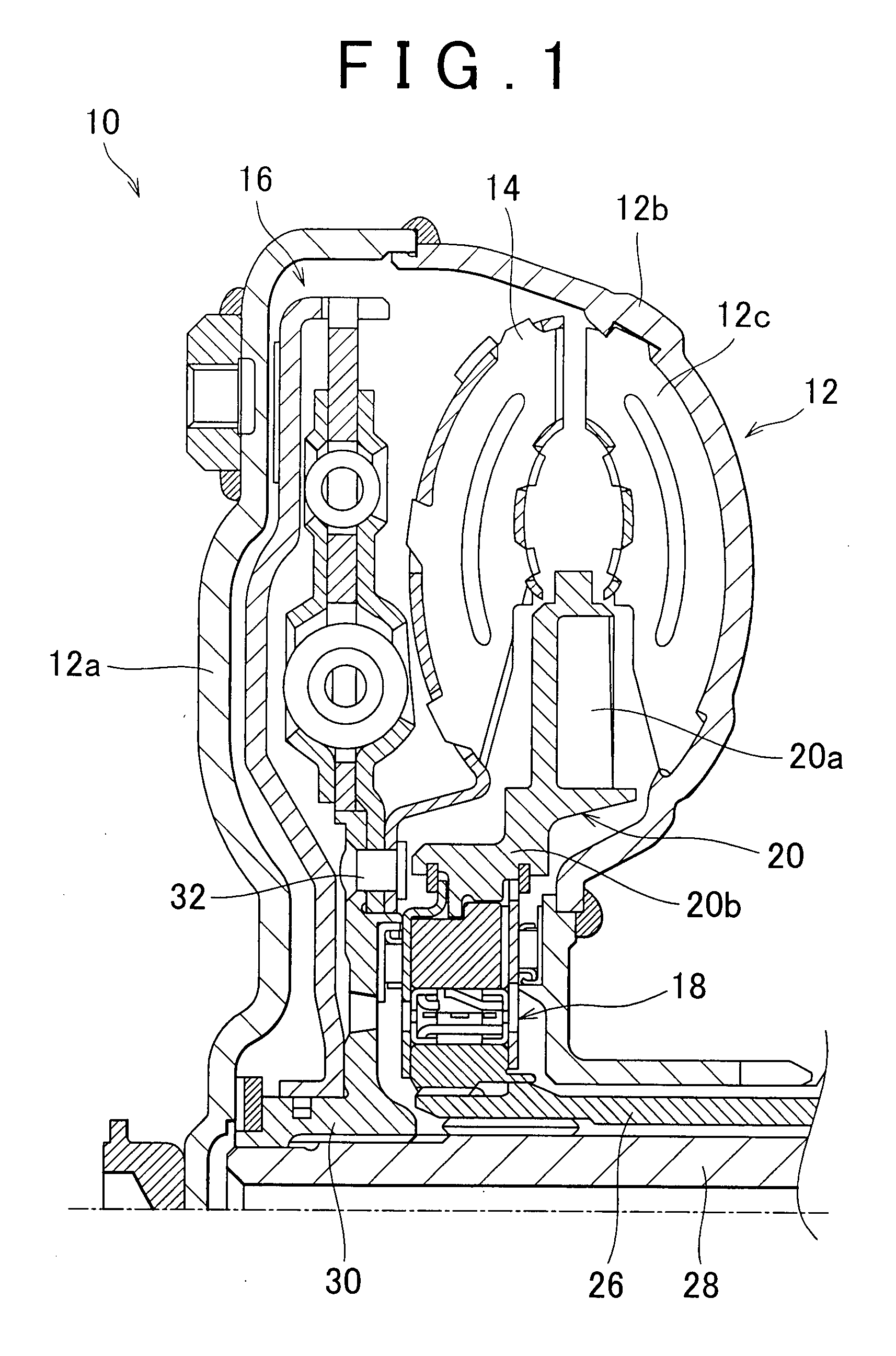
[0021]FIG. 1 is a cross-sectional view showing the configuration of a torque converter 10 according to an embodiment of the present invention. The torque converter 10 has a pump impeller 12, a turbine runner 14, a lock-up clutch 16, a one-way clutch 18, and a stator 20.

[0022]The pump impeller 12, for example, has a front case 12a, a rear case 12b, and an impeller wheel 12c. The front case 12a and the rear case 12b are linked to the crankshaft, to which the output of the engine (not illustrated) is transmitted, and are caused to rotate about their axes at the same rotational speed as the crankshaft. The impeller wheel 12c, having a plurality of blades, is provided around the circumference of the rear case 12b. When the engine rotates the front case 12a, the impeller wheel 12c of the pump impeller 12 is caused to rotate in concert with the front case 12a. By the rot...


PUM


Abstract

A stator support device for a torque converter having a stator wheel and a non-rotating member has a one-way clutch and a bearing race. The one-way clutch includes an outer race disposed along the inner periphery of the stator wheel, an inner race connected to the outer periphery of the non-rotating member to prevent rotation of the inner race relative to the non-rotating member, and an end bearing provided between the outer race and the inner race. The bearing race is disposed at a side face of the outer race. The bearing race is supported so as to be rotatable in the circumferential direction. A gap is formed between the bearing race and the stator wheel.

Description

INCORPORATION BY REFERENCE[0001]The disclosure of Japanese Patent Application No. 2006-242104 filed on Sep. 6, 2006, including the specification, drawings and abstract, is incorporated herein by reference in its entirety.BACKGROUND OF THE INVENTION[0002]1. Field of the Invention[0003]The present invention relates to a torque converter provided in a vehicle and particularly to a support structure for the stator of the torque converter.[0004]2. Description of the Related Art[0005]A torque converter, commonly provided in the power transmission path between the drive source and the automatic transmission of a vehicle, is a fluid drive device that multiplies the torque generated by the drive source and transmits the torque to the automatic transmission. A torque converter generally has a pump impeller that is rotatably driven by the drive source, such as an engine, a turbine runner that is rotated by operating fluid sent by the pump impeller, and a stator disposed between the pump impell...

Claims


Application Information

Patent Timeline
IPC IPC(8): F16H41/24F01M9/06
CPCF16H41/24F16H2045/0294F16H2045/0226F16H2041/246
Inventor OCHI, TORUTAKEUCHI, HIROAKISAKAMOTO, KENSUKE
Owner TOYOTA JIDOSHA KK
Why Eureka
Try Eureka