
Intrusion detection system for electric fences

a detection system and electric fence technology, applied in the field of intrusion detection systems, can solve the problems of difficult to gain access to the protected area without contacting the wires, detection is even slower, and the conductor of electric fences can be manipulated

Inactive Publication Date: 2008-08-07
PAKTON DEV
View PDF2 Cites 32 Cited by
  • Summary
  • Abstract
  • Description
  • Claims
  • Application Information

AI Technical Summary

Benefits of technology

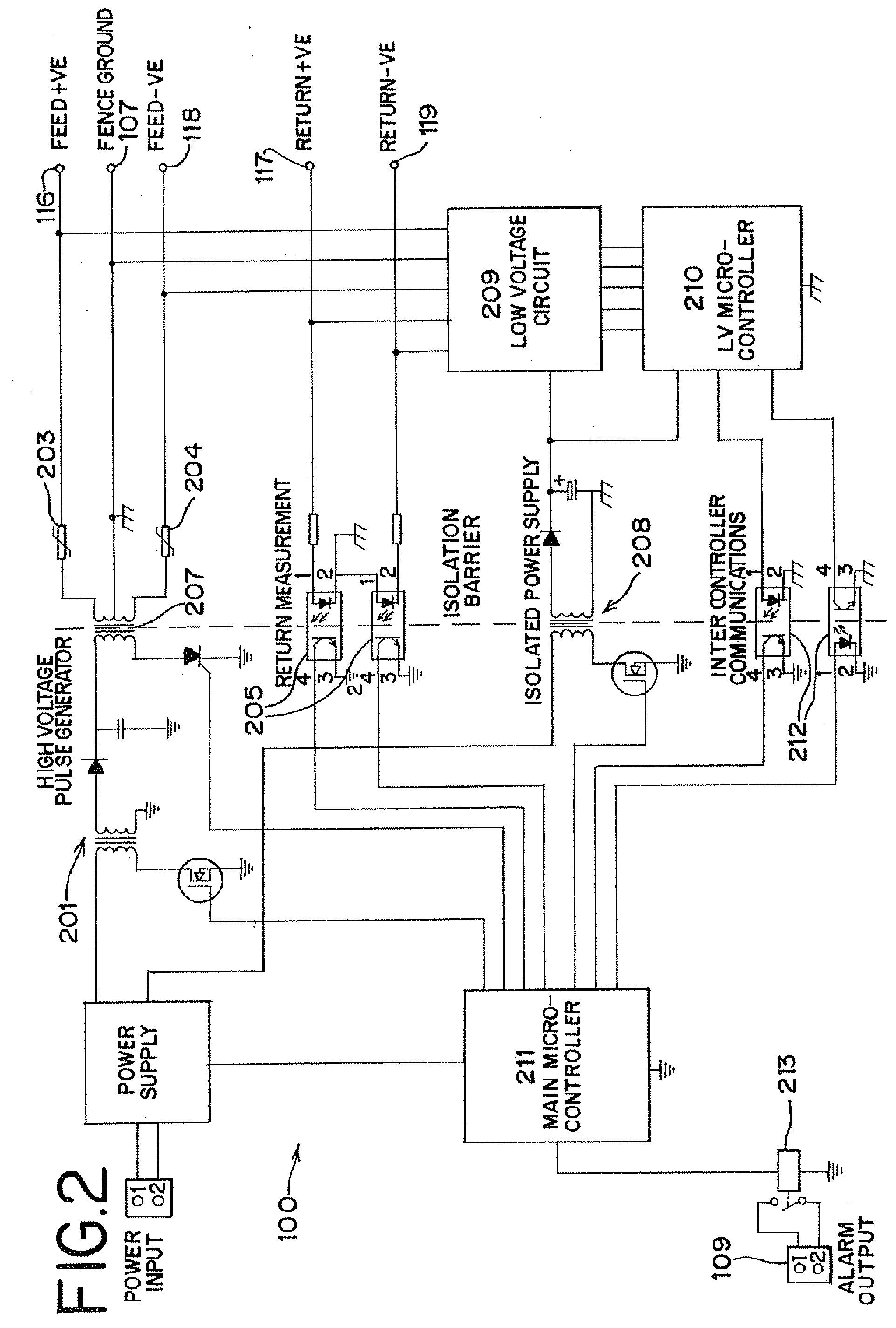
[0019]The present invention also includes methods of combining the output of the high voltage generator and the low voltage signal source onto the same fence output terminals and the high voltage monitor and low voltage monitor onto the same return terminals. The methods also include decoupling the pulse generator output transformer from the fence output terminals so as to not load down the low voltage signal. The methods further include protecting the sensitive circuitry of the low voltage monitor from the very high voltages of the conventional electric fence pulses without loading the high voltage down. The low voltage system measures the fence characteristics at a rapid rate enabling the detection of an intruder between the high voltage deterrent pulses.

Problems solved by technology

The spacing and height of the wires is such that it is difficult to gain access to the protected area without contacting the wires.
Since the detection is therefore also limited to this rate, the fence could be shorted quickly in between two pulses and it would not be detected.
In practice, the detection is even slower due the need to stop false alarms.
Problems may arise when the electric fence conductors can be manipulated or damaged when the energizer is off since the monitoring system is then incapable of detecting the problem.
Also damage to the fence will only be noticed when the system is armed again.
In some cases, these lower voltage pulses are still unacceptably high, such as on the order of several hundred volts peak.
While this is capable of detecting gross damage to the fence, it cannot detect all faults with the fence since these low voltage systems are usually merely measuring continuity of the ground conductors.
The reason that the ground circuit is chosen is that it is technically difficult to combine both a very low voltage and the conventional very high voltage pulse generator outputs onto the same fence circuit.
It therefore would present an unacceptable load on the low voltage power source.
This increases the likelihood of the intruder being deterred and or detected.
However, since there is no ground or earthed conductors in these fences, a prior art low voltage detection circuit cannot be added.
It is generally considered unsafe to use electric fences in a classified hazardous area.

Method used


Image

  • Intrusion detection system for electric fences
  • Intrusion detection system for electric fences
  • Intrusion detection system for electric fences

Examples


Embodiment Construction

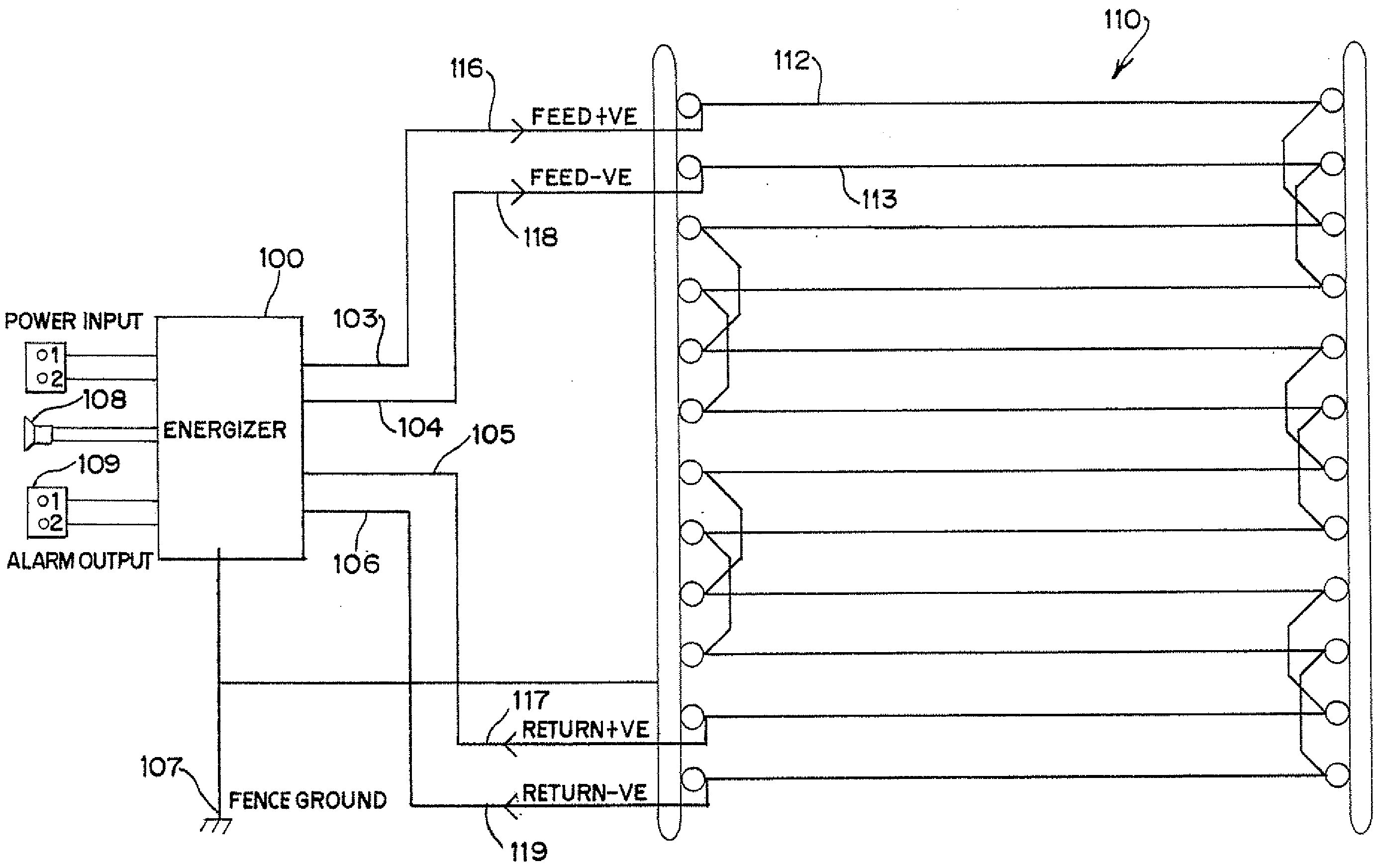
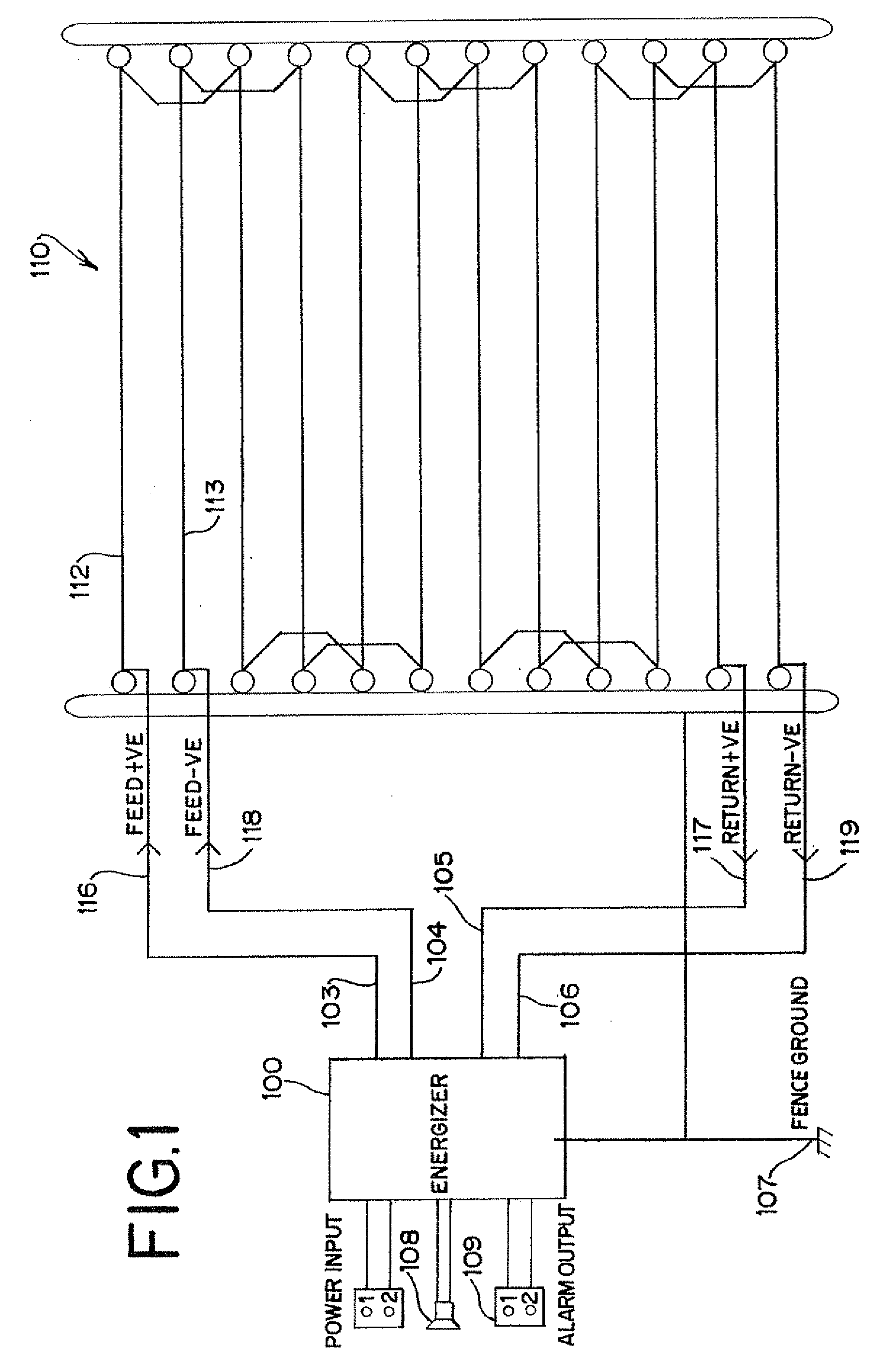
[0031]A diagrammatic view of a security electric fence, including a circuit schematic diagram, according to the preferred embodiment of the present invention is depicted in FIG. 1. An energizer 100 includes output terminals 103-106 to conduct both high voltage signals and low voltage signals onto the electric fence wires. The fence 110 contains two sets of live wires 112 and 113. A first “positive” channel runs from the positive feed terminal 116 to the fence 110, then down the fence 110 in an alternating pattern with the wires 112 to negative feed terminal 117. The positive wires terminate back to the positive return terminal 105. In similar fashion, A first “negative” channel runs from the negative feed terminal 118 to the fence 110, then down the fence 110 in an alternating pattern with the wires 113 to negative feed terminal 119. The negative wires terminate back to the negative return terminal 106. The energizer 100 also has a fence ground connection 107.

[0032]When the energize...


PUM


Abstract

An energizer for an electric fence having a wire with feed and return terminals. The energizer includes a high voltage pulse generator for generating high voltage pulses at the feed terminal and a low voltage circuit for providing a low voltage signal at the feed terminal and for monitoring any changes in the low voltage signal at the return terminal to determine if the wire of the fence is touched, or if a short circuit or open circuit exists. An impedance decouples the high voltage pulses from the low voltage circuitry. The low voltage circuit makes measurements of electrical characteristics of the wire between the high voltage pulses. A low voltage intrusion detection system and related methods are also disclosed.

Description

CROSS-REFERENCE TO RELATED PATENT APPLICATION[0001]This patent application is a non-provisional patent application of U.S. provisional patent application Ser. No. 60 / 887,731, filed on Feb. 1, 2007, the right of priority of which is claimed for this patent application.FIELD OF THE INVENTION[0002]The present invention relates to an intrusion detection system and in particular to electric fences and electric fence energizers.BACKGROUND OF THE INVENTION[0003]Electric fences are often for security purposes to restrict unauthorized entry to certain areas such as industrial premises. They are also used for containment in detention centers and for livestock and agricultural purposes.[0004]Electric fences normally include a number of posts from which numerous non-insulated wire conductors are strung such that the conductors are insulated from the posts and therefore the ground. The conductors are coupled to an energizer that periodically outputs a high voltage pulse to energize the conductor...

Claims


Application Information

Patent Timeline
IPC IPC(8): G08B13/00
CPCH05C3/00G08B13/26G08B13/122
Inventor THOMPSON, PAUL
Owner PAKTON DEV
Learn More