Method and Apparatus for Position Judgment
- Summary
- Abstract
- Description
- Claims
- Application Information
AI Technical Summary
Benefits of technology
Problems solved by technology
Method used
Image


Examples
Embodiment Construction
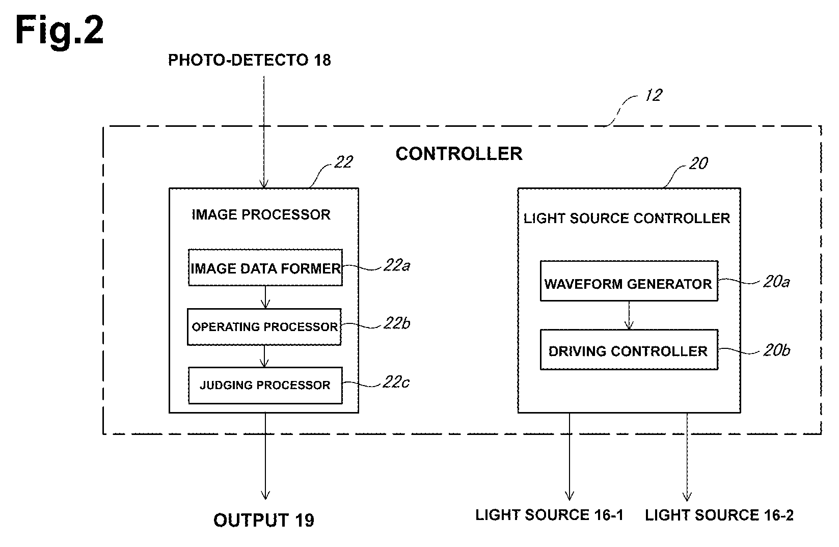
[0036]Exemplary embodiments of the disclosed subject matter will now be described in detail with reference to FIGS. 1-18. FIG. 1 is an explicative block diagram of a position judgment apparatus in accordance with a first exemplary embodiment of the disclosed subject matter.
[0037]A position judgment apparatus 10 in accordance with a first exemplary embodiment of the disclosed subject matter provides a controller 12 including a micro computer. The controller 12 can control the entire operation of the position judgment apparatus 10.
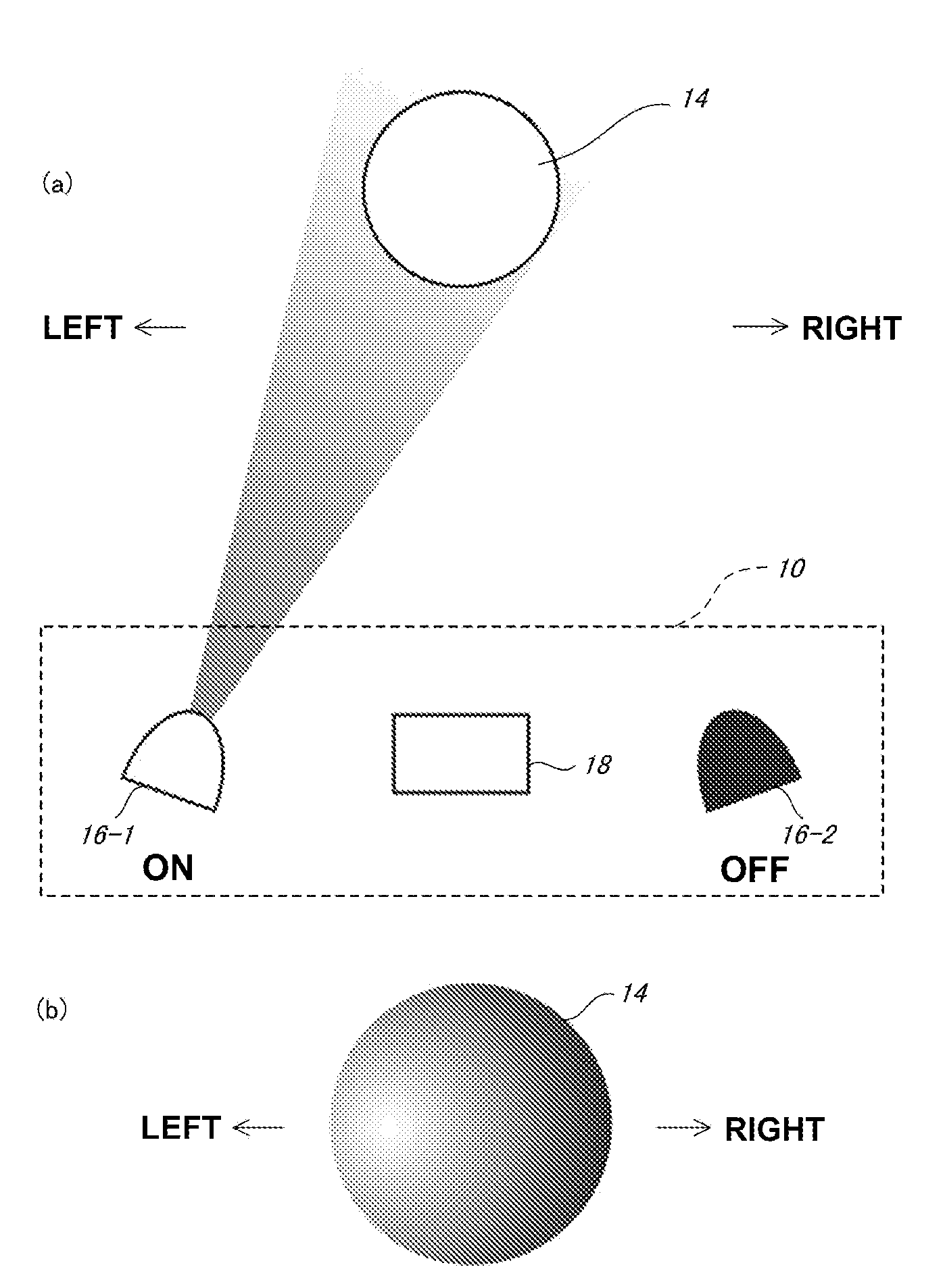
[0038]The position judgment apparatus 10 can also include: two light sources 16-1, 16-2 that emit respective light towards an object 14 by the controller 12; a photo-detector 18 configured to receive two reflex lights, which are reflected from the object 14 and which originated from the two light sources 16-1, 16-2; and an output 19 that is configured to input a judgment result outputted from the controller 12 and to inform the judgment result.
[0039]The ligh...
PUM
 Abstract
Description
Claims
Application Information