

Method and a Device For Measurement of Edges
- Summary
- Abstract
- Description
- Claims
- Application Information
AI Technical Summary
Benefits of technology
Problems solved by technology
Method used
Image

Examples
Embodiment Construction
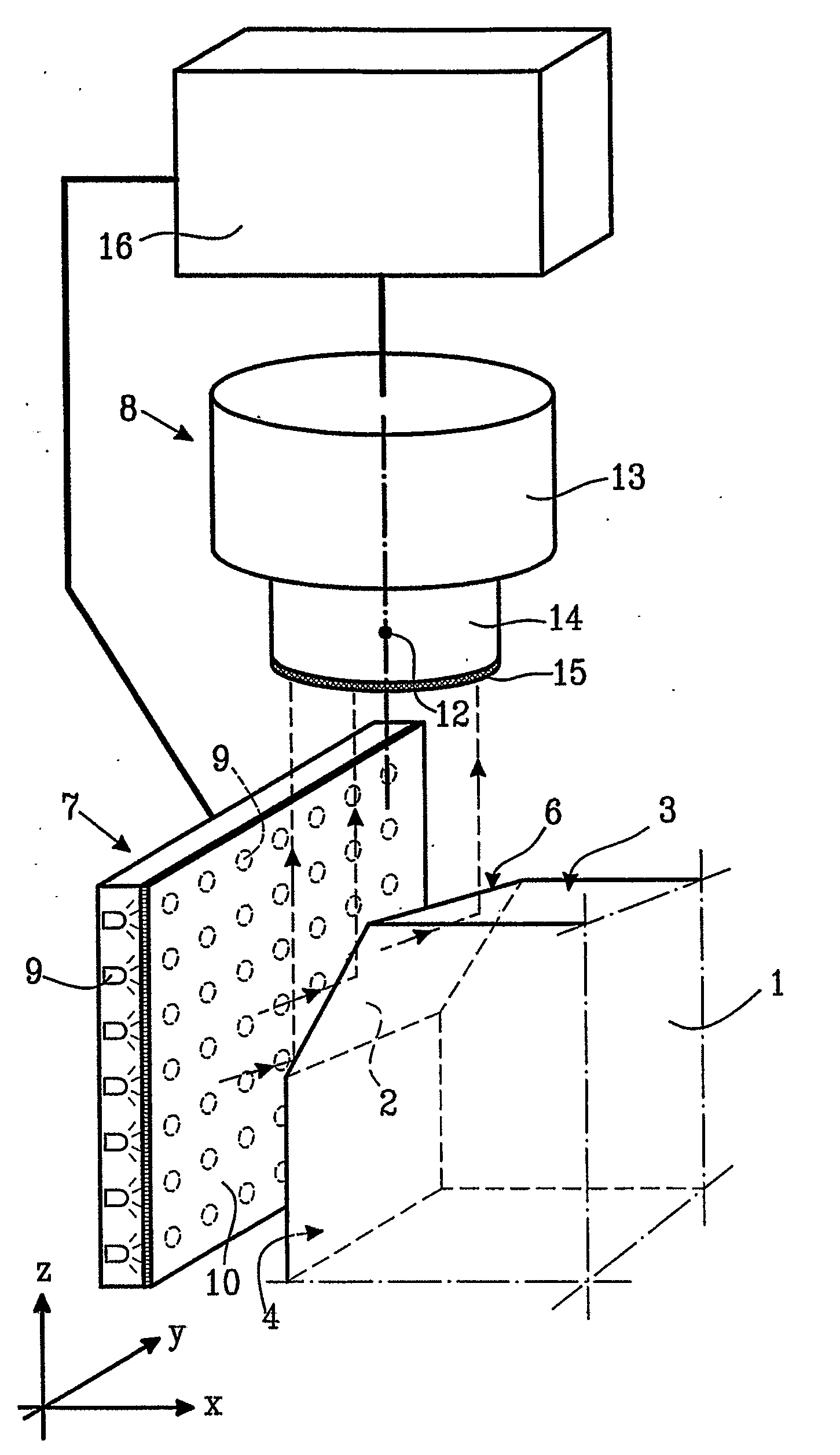
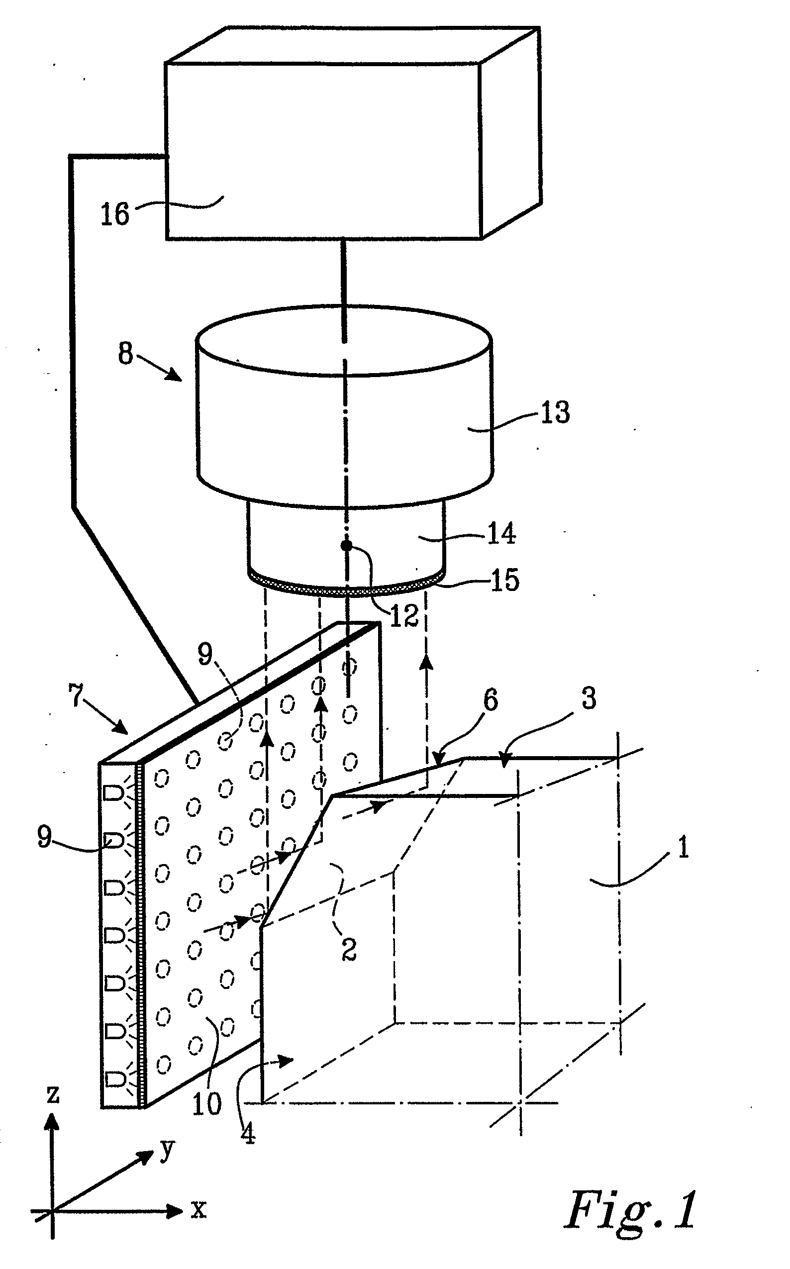
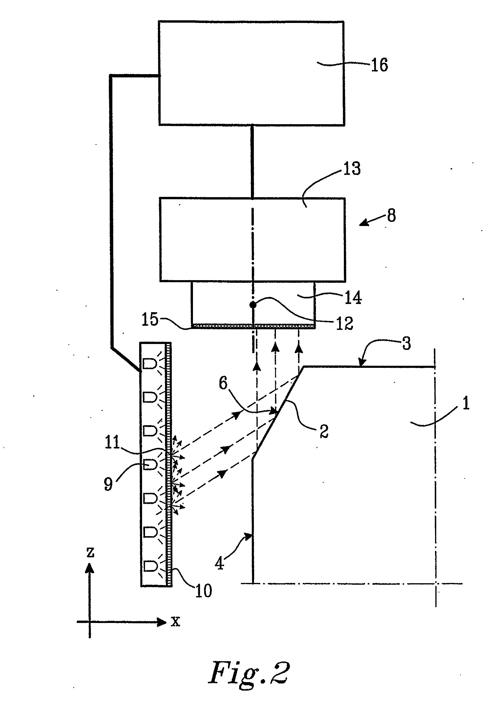
[0021]In FIGS. 1, 2 and 3, a component 1 to be depicted and measured is illustrated. The component 1 has a broken edge 2, and has further a first upper surface 3 and a second lateral surface 4. The component 1 can be a machined work piece or a cutting edge of a tool, for which the size or shape of the edge 2 is critical to the performance of the component or the tool.
[0022]In this example, the first and second surfaces 3, 4 are situated substantially perpendicular relative to each other. The edge 2 formed relatively close to the line (which line appears as a point 5 in FIG. 3) where the first and second surfaces theoretically intersect each other, is broken, thereby forming a third surface 6 of the component 1. The third surface 6 is flat and forms a first angle α, and a second angle β relative to the first and second surfaces, respectively, as appears from FIG. 3. This edge 2 having such a fiat surface 6 is only one example of an edge possible to be depicted by means of the method ...
PUM
 Abstract
Description
Claims
Application Information