Rotor blade trailing edge assembly and method of use

a technology of rotor blades and trailing edges, which is applied in the field of rotary blades, can solve the problems of difficult and time-consuming manufacture of known rotor blades, the damage of known large rotor blades, and the inability to finish fiberglass trailing edges to less than two-and-a-half millimeters

Active Publication Date: 2008-08-07
GENERAL ELECTRIC CO
View PDF11 Cites 105 Cited by
  • Summary
  • Abstract
  • Description
  • Claims
  • Application Information

AI Technical Summary

Problems solved by technology

Known rotor blades are generally difficult and time consuming to manufacture.
However, due to the poor structural characteristics of fiberglass, when the shells are fitted together the trailing edge usually requires additional finishing for defining a finished trailing edge width.
Using contemporary techniques, known fiberglass trailing edges generally cannot be finished to less than two-and-a-half millimeters.
The trailing edge is generally the weakest region of a rotor blade and its width may also contribute to noise generated by the rotor blades during wind turbine operation.
Because of their size and / or fragility, some known large rotor blades may be damaged during transportation.
For example, the trailing edge of some known rotor blades may be damaged during loading and / or unloading into and / or unloading from at least some known transportation containers, or during installation.
Additionally, because rotor blades are much longer than wide, rotor blades are susceptible to buckling during operation as well as during transportation and installation.

Method used


Image

  • Rotor blade trailing edge assembly and method of use
  • Rotor blade trailing edge assembly and method of use
  • Rotor blade trailing edge assembly and method of use

Examples


Embodiment Construction

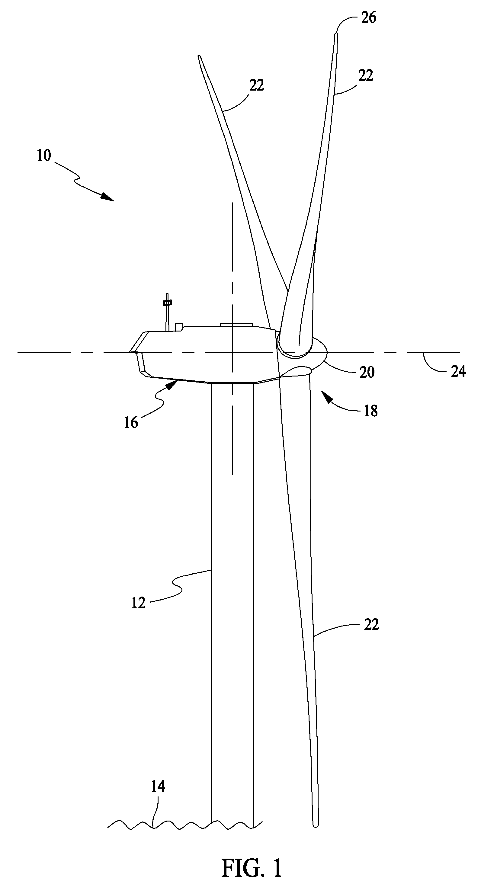
[0021]FIG. 1 is a schematic illustration of an exemplary wind turbine generator 10. In the exemplary embodiment, wind turbine generator 10 is a horizontal axis wind turbine. Alternatively, wind turbine 10 may be a vertical axis wind turbine. Wind turbine 10 has a tower 12 extending from a supporting surface 14, a nacelle 16 mounted on tower 12, and a rotor 18 coupled to nacelle 16. Rotor 18 has a rotatable hub 20 and a plurality of rotor blades 22 coupled to hub 20. In the exemplary embodiment, rotor 18 has three rotor blades 22. In an alternative embodiment, rotor 18 may have more or less than three rotor blades 22. A center line 24 extends through nacelle 16 and hub 20. Each rotor blade 22 includes a tip 26. In the exemplary embodiment, tower 12 is fabricated from tubular steel and has a cavity (not shown in FIG. 1) extending between supporting surface 14 and nacelle 16. In an alternate embodiment, tower 12 is a lattice tower. The height of tower 12 is selected based upon factors ...


PUM

PropertyMeasurementUnit
lengthaaaaaaaaaa
lengthaaaaaaaaaa
pressureaaaaaaaaaa

Abstract

A method of assembling a rotor blade for a turbine is provided that includes forming a rotor blade trailing edge by coupling a suction side terminus to a pressure side terminus and positioning a trailing edge assembly between the suction side terminus and the pressure side terminus, the trailing edge assembly having a varying cross-section.

Description

BACKGROUND OF THE INVENTION[0001]This invention relates generally to rotary blades, and more particularly, to a rotor blade trailing edge assembly and method of use.[0002]Generally, a wind turbine generator includes a rotor having multiple blades. The rotor is sometimes mounted within a housing, or nacelle, that is positioned on top of a base, for example a truss or tubular tower. At least some known utility grade wind turbines (i.e., wind turbines designed to provide electrical power to a utility grid) can have rotor blades of 30 meters (m) (100 feet (ft)) or more in length.[0003]Known rotor blades are generally difficult and time consuming to manufacture. They are generally manufactured from two molded fiberglass shells fitted together to define a blade cross section having a leading edge and a trailing edge. However, due to the poor structural characteristics of fiberglass, when the shells are fitted together the trailing edge usually requires additional finishing for defining a ...

Claims


Application Information

Patent Timeline
Patent Type & Authority Applications(United States)
IPC IPC(8): F01D5/14B23P17/00
CPCF03D1/001F03D1/065F05B2260/02Y10T29/49321Y02E10/721Y02E10/728F05B2260/96F05B2250/183F03D13/10Y02E10/72
Inventor STANDISH, KEVIN JAMESHERR, STEFANALTHOFF, NICHOLAS KEANELIVINGSTON, JAMIE THOMAS
Owner GENERAL ELECTRIC CO
Why Eureka
Try Eureka