Luer-lock type cykindrical tip of syringe

Inactive Publication Date: 2008-08-07
ARTE
View PDF11 Cites 53 Cited by
  • Summary
  • Abstract
  • Description
  • Claims
  • Application Information

AI Technical Summary

Benefits of technology

[0016]With the luer-lock type cylindrical tip according to the first aspect, it is possible to increase the height of the thread of the lock screw of the luer-lock portion. When the needle base of the injection needle is fitted to the luer tip to screw the screwing protrusion of the needle base to the lock screw, it is possible to enhance the area of a contact portion between the lock screw and the screwing protrusion, thereby increasing the frictional force acting on the contact portion. Accordingly, in the handling process after the injection needle is fitted to the cylindrical tip of the syringe in the manufacturing site and until the syringe is used in the medical scene or the like, it is possible to reliably prevent the injection needle from being loosened or pulled out relative to the cylindrical tip due to vibration or the like. In the lock screw, the inner diameter and pitch of the thread are slightly different from those prescribed in the ISO standard and other values can be set equal to those of the ISO standard can be employed. As a result, at the time of use, a user can easily replace the injection needle of the syringe with commercially available injection needles having dimensions corresponding to the ISO standard.
[0017]In addition, it is possible to increase the height of the thread of the lock screw of the luer-lock portion and to increase the thicknesses of the bottom and top of the thread. Accordingly, in the handling process, it is possible to reliably prevent the injection needles fitted to the cylindrical tip from being loosened or pulled out. Furthermore, it is possible to enhance the holding force of the lock screw for holding the injection needle in the cylin

Problems solved by technology

However, the injection needle becomes easily loosened and pulled out during these operations or during transport through the distribution channel.
However, the shape of the screwing portion between the lock screw and the needle base of the injection needle is not considered at all.
Accordingly, in the handling pr

Method used


Image

  • Luer-lock type cykindrical tip of syringe
  • Luer-lock type cykindrical tip of syringe
  • Luer-lock type cykindrical tip of syringe

Examples


Example

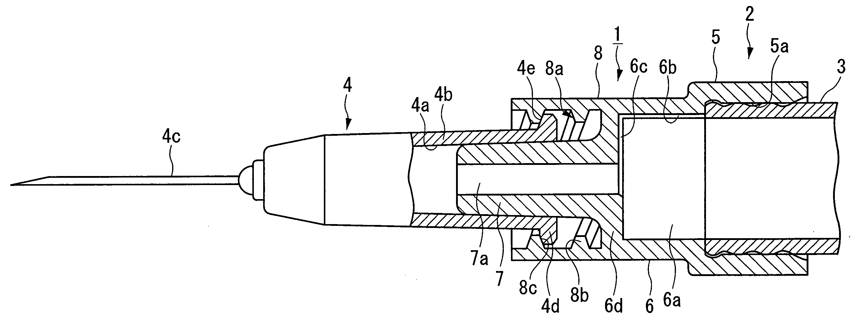
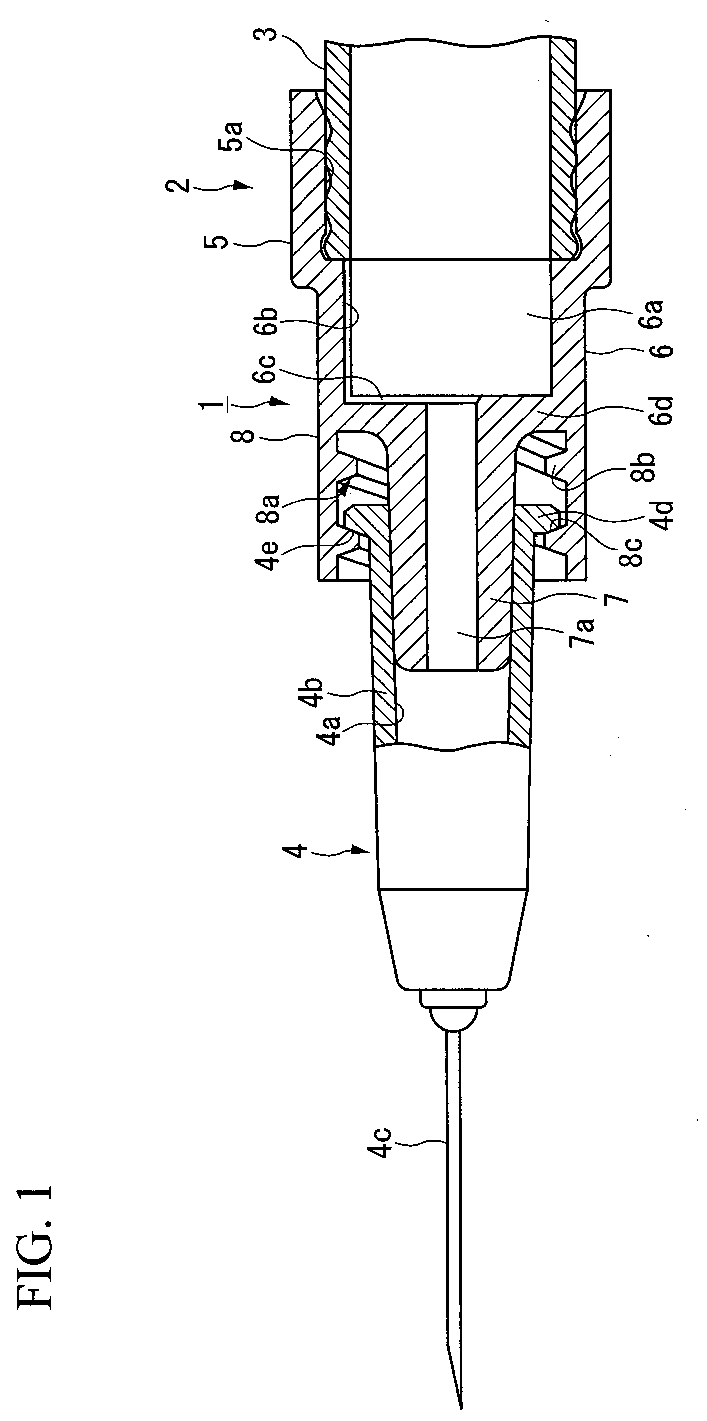
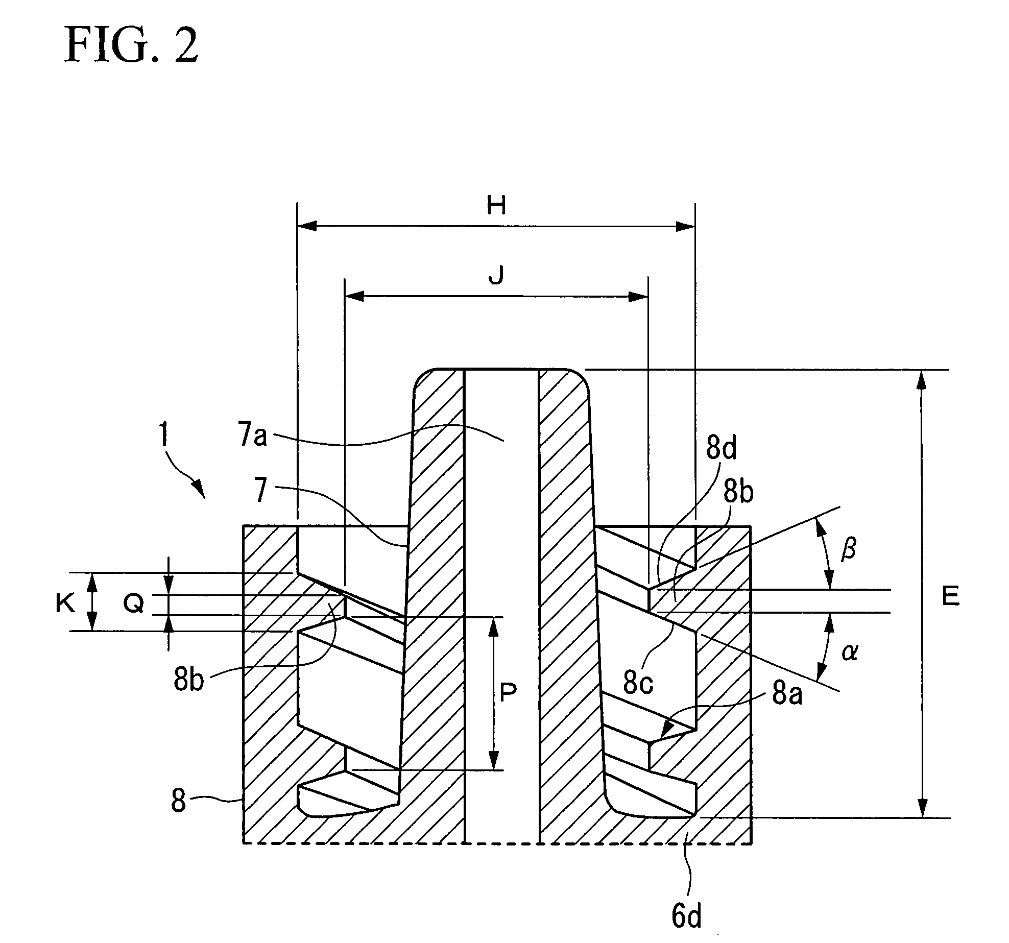
[0023]Hereinafter, a luer-lock type cylindrical tip of a syringe according to an embodiment of the invention will be described with reference to the attached drawings.

[0024]In FIG. 1, reference numeral 1 denotes a luer-lock type cylindrical tip of a syringe according to an embodiment of the invention, which is fitted to the outer periphery of a front end (left end in FIG. 1) of a cylinder 3 of a combined container-syringe (syringe) 2. Although not shown in detail, the combined container-syringe 2 further includes a finger grip disposed at the rear end of the cylinder 3, a front stopper and a rear stopper which are inserted into the cylinder 3 so as to reciprocate in the axis direction thereof and which seal a drug solution or drug product filled in the cylinder 3, a plunger rod which is inserted into the cylinder 3 from the rear side so as to connect the front end portion thereof to the rear stopper and to allow the rear stopper to reciprocate in the axis direction of the cylinder 3...


PUM


Abstract

A luer-lock type cylindrical tip of a syringe has a luer tip of which a center portion is fitted with an injection needle and a luer-lock portion which is disposed outside the luer tip with a gap therebetween and which has a lock screw disposed therein. The lock screw is formed as a trapezoid screw having a root diameter set to the range of 8.0 mm±0.1 mm, an inner diameter set to the range greater than or equal to 6.6 mm and smaller than 6.8 mm, and a pitch set to the range greater than 2.5 mm and smaller than or equal to 2.8 mm. Accordingly, it is possible to reliably prevent the injection needle from being loosened or pulled out in the handling process. It is also possible to easily replace the syringe needle with another one having different size at the time of use.

Description

BACKGROUND OF THE INVENTION[0001]1. Field of the Invention[0002]The present invention relates to a luer-lock type cylindrical tip of a syringe having a luer-lock portion which can strongly hold an injection needle fitted to a luer tip.[0003]Priority is claimed on Japanese Patent Application No. 2006-308817, filed Nov. 15, 2006, the content of which is incorporated herein by reference.[0004]2. Description of the Related Art[0005]The combined container-syringes are delivered to the pharmaceutical company in a state such that the injection needles are attached in advance to the luer-lock type cylindrical tips. The delivered combined container-syringes are sterilized at the pharmaceutical company. After sterilization, operations such as filling the syringes with the drug solution, assembly, inspection, and packaging are automatically and speedily performed by machine. The injection needles which have been attached to the cylindrical tips are loosened by mechanical vibration or load more...

Claims


Application Information

Patent Timeline
IPC IPC(8): A61M5/34
CPCA61M5/347A61M5/34
Inventor SHIMAZAKI, SEIJITAKESHIMA, YASUHIKO
Owner ARTE
Why Eureka
Try Eureka