System and method for repairing tendons and ligaments

a technology for tendons and ligaments, applied in the field of surgical repair of torn tendons and ligaments, can solve the problems of 20-60% of rotator cuff repairs fail, and excess material or insufficient strength, etc., to achieve minimal detrimental tissue response during absorption, relieve the load of a tendon, and absorb over long periods of time

Inactive Publication Date: 2008-08-07
TORNIER INC
View PDF96 Cites 416 Cited by
  • Summary
  • Abstract
  • Description
  • Claims
  • Application Information

AI Technical Summary

Benefits of technology

[0023]The present method and implant relieves at least part of the separation forces experienced by the repair during the recovery period. The implant is preferably absorbed by the body after healing. The implant preferably distributes the separation forces experienced by a ligament or tendon-to-bone surgical repair during the recovery period over a large area of the ligament or tendon. The implant preferably includes reinforced regions in it construction to distribute attachment loads of sutures and prevent sutures from tearing through the device.
[0042]In another embodiment the implant includes a patch material with a first edge and a second edge. At least one elongated slot is located in the patch material between the first and second edges. A suture material is laced along opposite edges of the elongated slot so that tension on the suture material reduces the elongated slot and increases tension between the first and second edges along a load direction.

Problems solved by technology

This state-of-the-art repair is subject to a 20-60% failure rate, primarily due to suture tear-out through poor quality tendon tissue.
The isotropic nature of the patch 60 results either in bulky excess material or insufficient strength along the direction of loading 68.
In spite of numerous recent advances in primary fixation repair, 20-60% of rotator cuff repairs fail, primarily due to suture tear-out in poor quality tendon tissue.
The case of retracted tissue presents a particular challenge to the surgeon since tendon of poor quality must be placed in tension to move it into apposition with the footprint, making it particularly prone to failure.
This approach can provide structural reinforcement through out the healing period, but leaves behind a permanent device with all the abrasion, adhesion, migration and rejection issues associated with foreign bodies.
Additionally, it has been shown that reinforcements that completely relieve the anatomic loads on the tendon or ligament lead to atrophy of the tissue.
However, the absorption characteristics of these materials can result in crystallization of the degrading polymer and acidification of surrounding tissue causing inflammation and tissue reactions.
Further, most commonly available absorbable polymers loose most of their strength in 6 weeks or less, long before healing of the ligament or tendon-to-bone is complete.
First, though every attempt has been made to sterilize the material, infection and disease transmission has been observed.
Second, even in sterile implants, foreign body reactions such as severe inflammation occur on a regular basis.
Third, the tensile strength and elastic properties of most of these materials has been shown to be insufficient to provide any meaningful reinforcement.
Fourth, most biomaterials have been shown to absorb long before healing is complete.
Finally, while cell repopulation has been shown to occur, they tend to be mostly scar tissue and not the desired strong, highly oriented cellular structure of the host ligament or tendon tissue.
Since the anatomic loads in ligament and tendons occur in distinct directions, corresponding to the anisotropic orientation of the cellular structure of the ligament or tendon itself, construction elements (filaments, cells, etc.) that are directional in nature and are not aligned with the tissue loads do not efficiently contribute to the strength of the device and only serve to bulk up the amount of foreign body material in the implant.
Again this results in unnecessary foreign body material bulk in the implant.
In addition to the inherent biologic burden associated with excess implant material, additional bulk impedes the ability of the implant to be manipulated in confined spaces, such as passing through an arthroscopic cannula.
Many of the thicker implants are therefore limited to implantation by open surgery, rather than by less invasive arthroscopic surgical techniques.
The result of stitching a planar augmentation graft to a roughly spherical tendon surface is localized puckering of the graft material, potentially resulting in impingement and interference with surrounding tissue.

Method used


Image

  • System and method for repairing tendons and ligaments
  • System and method for repairing tendons and ligaments
  • System and method for repairing tendons and ligaments

Examples


Embodiment Construction

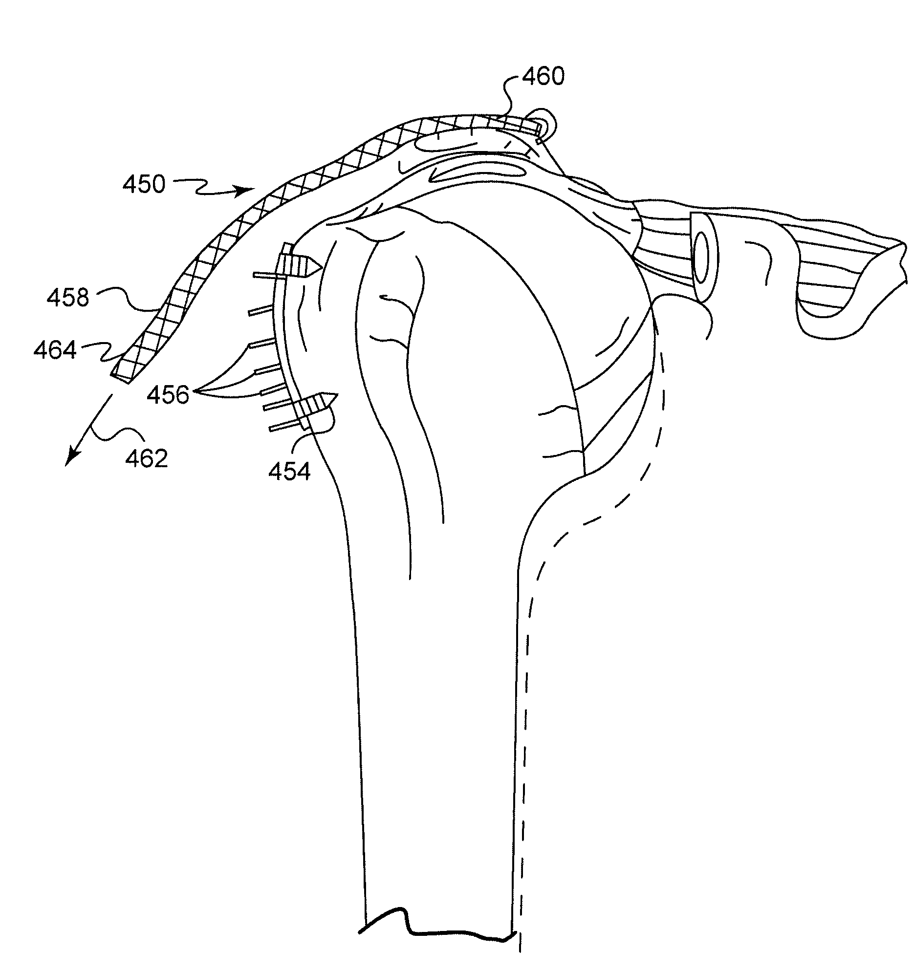
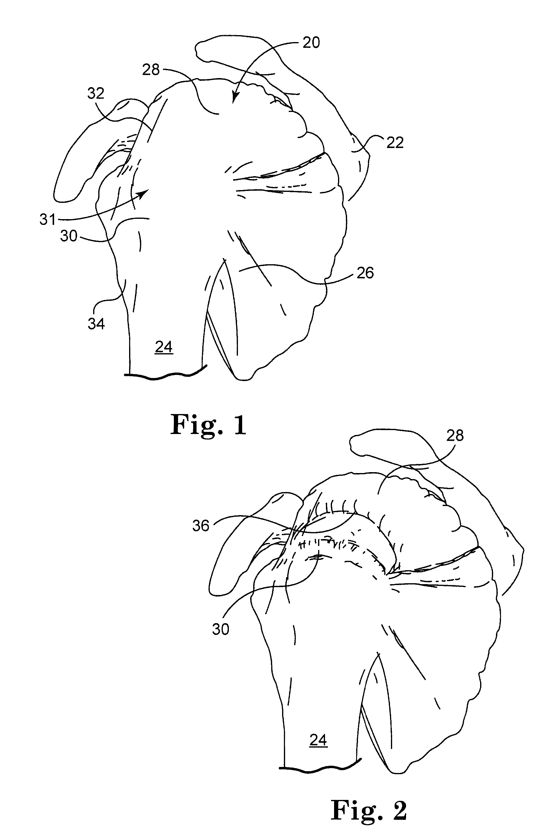
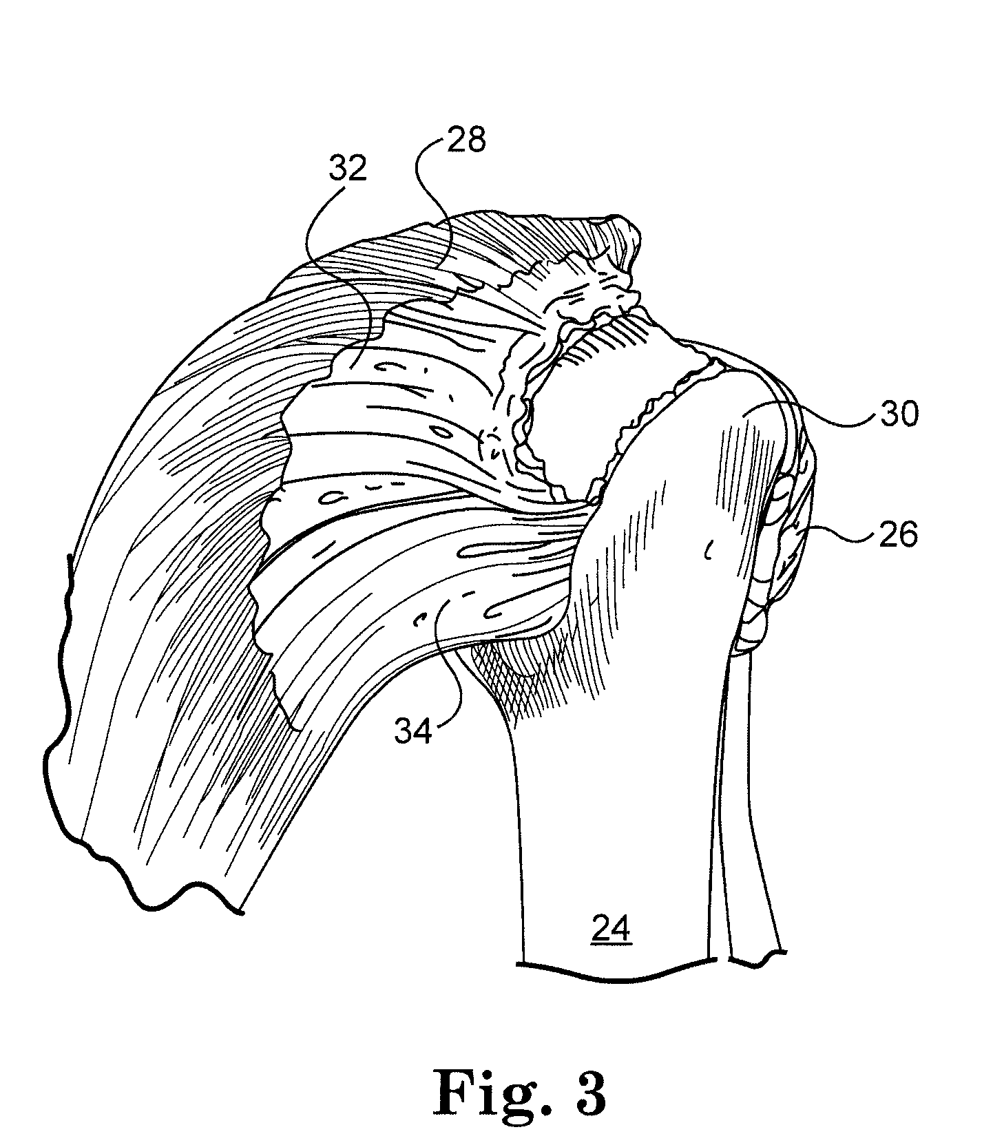
[0077]The present method and apparatus can be used to repair and reconstruct torn ligaments and tendons in a variety of locations of the body. The rotator cuff muscles were selected for the exemplary embodiments because of the complexity of the human shoulder. It will be appreciated that the following method and apparatus has many other possible applications.

[0078]FIG. 6 shows a bioabsorbable implant 70 made from a patch material 72 in accordance with an embodiment of the present invention. Implant 70 includes first and second edges 74, 76, and first and second side edges 78, 80. In a rotator cuff application, the implant 70 includes lateral edge 74, medial edge 76, anterior edge 78, and posterior 80 edges. The lateral edge (i.e., first edge) 74 and medial edge (i.e., second edge) 76 are preferably reinforced to facilitate attachment. The anterior 78 and posterior edges 80 (i.e., the side edges) are also optionally reinforced.

[0079]In some embodiments the anterior and posterior edge...


PUM


Abstract

An implant and method for the repair of a tendon or a ligament along at least one load direction. The implant includes at least one first anchor portion and at least one tension member oriented along a load direction. The first anchor portion preferably has a larger surface area of engagement with the tendon or ligament to spread loads across more tissue. The tension member is preferably secured to the first anchor portion with an overlapping attachment. Tension on the tension member is preferably adjustable by the surgeon.

Description

[0001]The present application claims the benefit of U.S. Provisional Application Ser. Nos. 60 / 899,099, entitled Ligament and Tendon-to-Bone Repair Augmentation Device, filed Feb. 2, 2007, 60 / 900,402, entitled Thermally Welded Fabric Assembly and Method, filed Feb. 9, 2007 and 60 / 900,403, entitled Fabric-to-Bone Thermal Weld System and Method, filed Feb. 9, 2007, the complete disclosures of which are hereby incorporated by reference.FIELD OF THE INVENTION[0002]The present invention relates to surgical repair of torn tendons and ligaments in an animal, and in particular, to open and arthroscopic orthopedic surgical repair of torn tendons and ligaments in the body, such as arthroscopic repair of torn rotator cuff tissue in the human shoulder.BACKGROUND OF THE INVENTION[0003]As illustrated in FIG. 1, the rotator cuff 20 is the complex of four muscles that arise from the scapula 22 and whose tendons blend in with the subjacent capsule as they attach to the tuberosities of the humerus 24....

Claims


Application Information

Patent Timeline
Patent Type & Authority Applications(United States)
IPC IPC(8): A61F2/08
CPCA61B17/1146A61B2017/0404A61F2/08A61B2017/0496A61F2/0063A61B2017/0417A61F2220/0075
Inventor BALL, ROBERT J.EGAN, THOMAS D.FENTON, PAUL V.OHASHI, KEVIN L.PETERSON, DALE R.SORENSON, PETERSNELL, DOUGLASYANNONE, JOHNFENTON, PATRICK
Owner TORNIER INC
Why Eureka
Try Eureka