Program execution device and electronic apparatus
- Summary
- Abstract
- Description
- Claims
- Application Information
AI Technical Summary
Benefits of technology
Problems solved by technology
Method used
Image
Examples
embodiment example 1
[0039]Structure
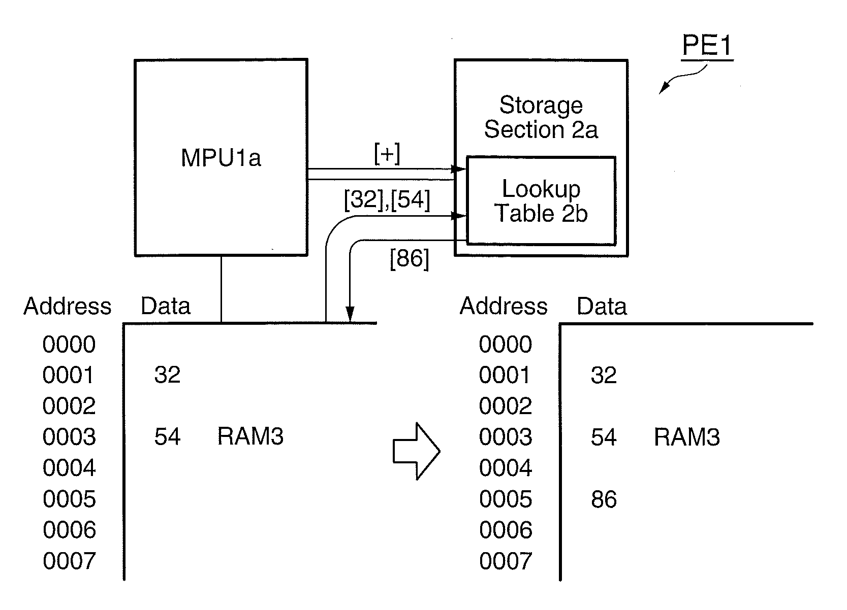
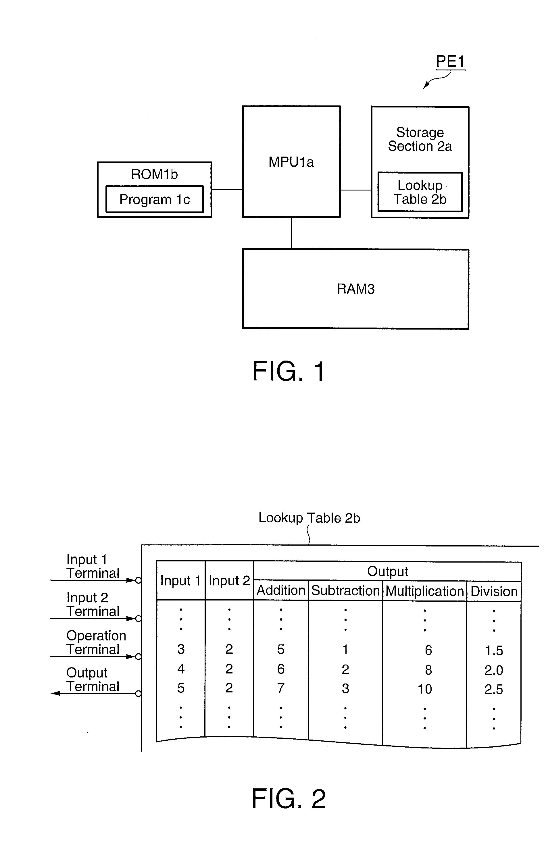
[0040]FIG. 1 shows the structure of a program execution device PE1 in accordance with Embodiment Example 1. The program execution device PE1 includes a MPU 1a, a ROM 1b, a storage section 2a and a RAM 3, as shown in FIG. 1.
[0041]The MPU 1a is a “program execution section,” and executes a program 1c stored in the ROM 1b.
[0042]The ROM 1b is a “program storage section,” and stores a program 1c including a command 9 and a command 14 to be executed by the MPU 1a, like the ROM 10b of related art shown in FIG. 10 and FIG. 12.
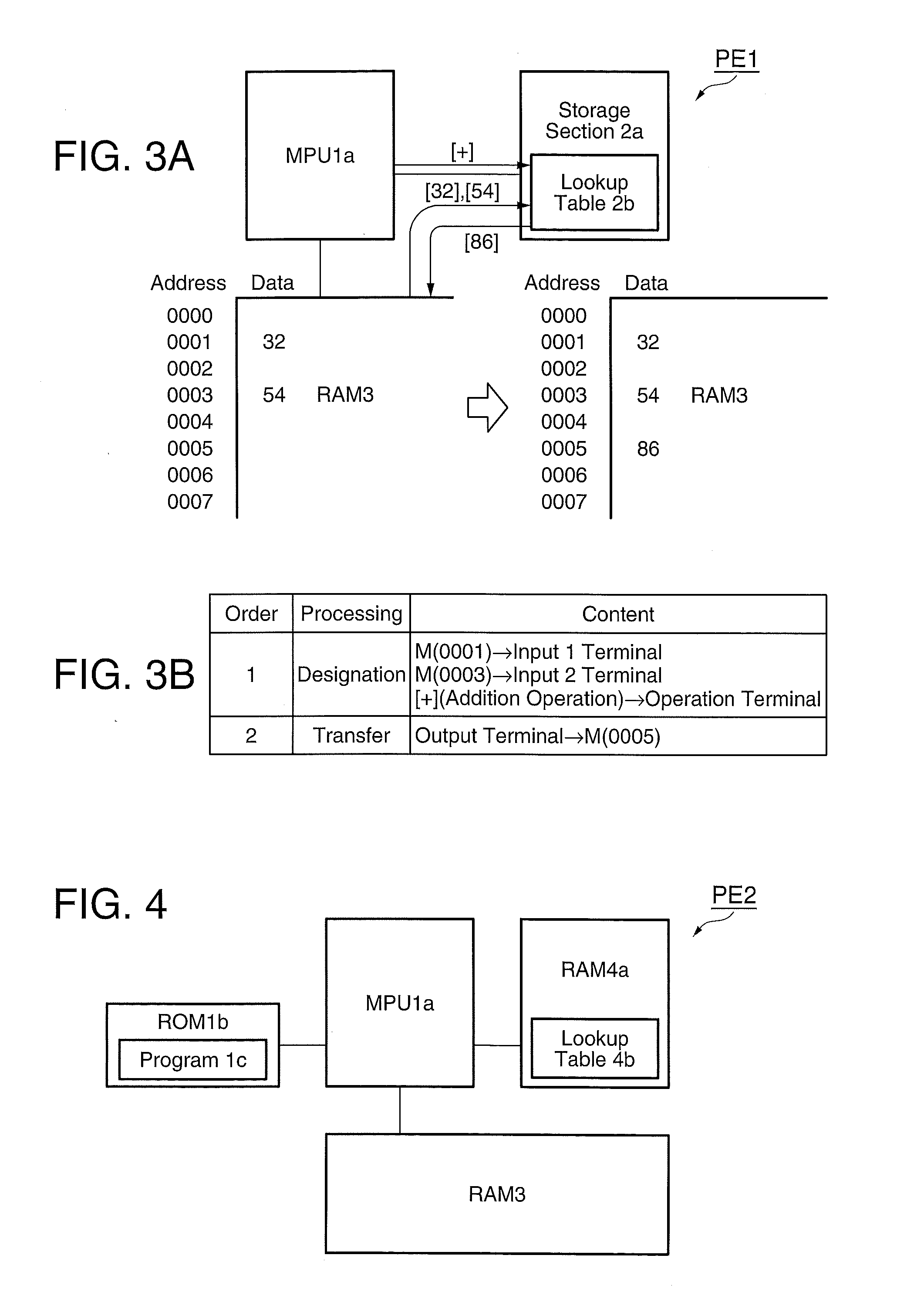
[0043]The storage section 2a is a “lookup table storage section,” and stores a lookup table 1b to be referred to by the MPU 1a when executing the program 1c. As shown in FIG. 2, the lookup table 2b has an input 1 terminal that receives a designation of input data as “input 1,” an input terminal 2 that receives a designation of input data as “input 2,” an operation terminal that receives a designation of the kind of “operation” (addition, subtraction, mu...
embodiment example 2
[0053]Structure
[0054]FIG. 4 shows the structure of a program execution device PE2 in accordance with Embodiment Example 2. It is clear from the comparison between the program execution device PE1 of Embodiment Example 1 shown in FIG. 1 and the program execution device PE2 of Embodiment Example 2 shown in FIG. 4 that the program execution device PE2 in accordance with Embodiment Example 2 includes a MPU 1a, a ROM 1b, a program 1c and a RAM 3, like the program execution device PE1 of Embodiment Example 1, and on the other hand includes a RAM 4a that is a rewritable memory and a lookup table 4b, instead of the storage section 2a and the lookup table 2b, for processing (for example, rendering correction of saturation and luminosity on), for example, images of a changing object to be photographed (for example, scenes and person), which is different from the program execution device PE1 of Embodiment Example 1.
[0055]In order to change the contents of processing to be rendered on the photo...
embodiment example 3
[0064]Structure
[0065]FIG. 6 shows the structure of a program execution device PE3 in accordance with Embodiment Example 3. As shown in FIG. 6, the program execution device PE3 in accordance with Embodiment Example 3 includes a MPU 1a, a ROM 1b, a program 1c and a RAM 3, like the program execution devices PE1 and PE2 of Embodiment Example 1 and Embodiment Example 2, and on the other hand includes a FeRAM 5a that is a ferroelectric memory having nonvolatility and a lookup table 5b, instead of the storage section 2a and the lookup table 2b, and the RAM 4a and the lookup table 4b, which are different from the program execution devices PE1 and PE2 of Embodiment Example 1 and Embodiment Example 2.
[0066]The lookup table 5b stored in the FeRAM 5a stipulates, as shown in FIG. 7, an “addition with weighting” similar to that of the lookup table 4b of Embodiment Example 2, and is sequentially changed from a lookup table 5b (1), to a lookup table 5b (2), to a lookup table 5b (3), to a lookup tab...
PUM
 Abstract
Description
Claims
Application Information
 - R&D Engineer
- R&D Manager
- IP Professional
- Industry Leading Data Capabilities
- Powerful AI technology
- Patent DNA Extraction
Browse by: Latest US Patents, China's latest patents, Technical Efficacy Thesaurus, Application Domain, Technology Topic, Popular Technical Reports.
© 2024 PatSnap. All rights reserved.Legal|Privacy policy|Modern Slavery Act Transparency Statement|Sitemap|About US| Contact US: help@patsnap.com


