Element of a cable tie strap

a tie strap and cable technology, applied in the direction of snap fasteners, hose connections, machine supports, etc., can solve the problems of reducing the service life of the tie strap, so as to reduce the amount of wall thickness, shorten the production cycle time, and achieve the effect of desired structural integrity

Active Publication Date: 2008-08-14
HELLERMANNTYTON CORP
View PDF37 Cites 12 Cited by
  • Summary
  • Abstract
  • Description
  • Claims
  • Application Information

AI Technical Summary

Benefits of technology

[0009]To achieve the desired characteristics, the low profile locking tie head of the present invention comprises a reduced amount of wall thickness while maintaining desired structural integrity. The reduction of the wall thickness allows for the shortening of production cycle time and further allows for material savings and desirable installation and maintenance characteristics.
[0010]The reduction of wall thickness and material is achieved by using a reinforcement rib, which is integrally formed with the low profile locking tie head wall. The reinforcement rib can be used alone or in connection with clamping rails on the underside of the tie head. Clamping rails allow an even greater reduction in head height, thereby reducing even further the protrusion from the surface of a bundle of objects.

Problems solved by technology

Primarily, such tie heads have been relatively bulky, thereby leading to at least three problems.
Second, previous tie head bulk provided undesirable obstruction in a variety of applications.
Such heads would not allow passage of bundled items through wire looms, frame rails and channels.
Furthermore, due to their protrusion from a bundle, such heads could cause injury to persons installing bundles or maintaining equipment containing the bundles.
Finally, obstruction of previous tie heads affected the wire density in a given routing location.
That is, since prior tie heads were bulky, the obvious protrusion of the head from the bundle would consume valuable routing space, which would otherwise be filled with wires or cables.

Method used


Image

  • Element of a cable tie strap
  • Element of a cable tie strap
  • Element of a cable tie strap

Examples


Embodiment Construction

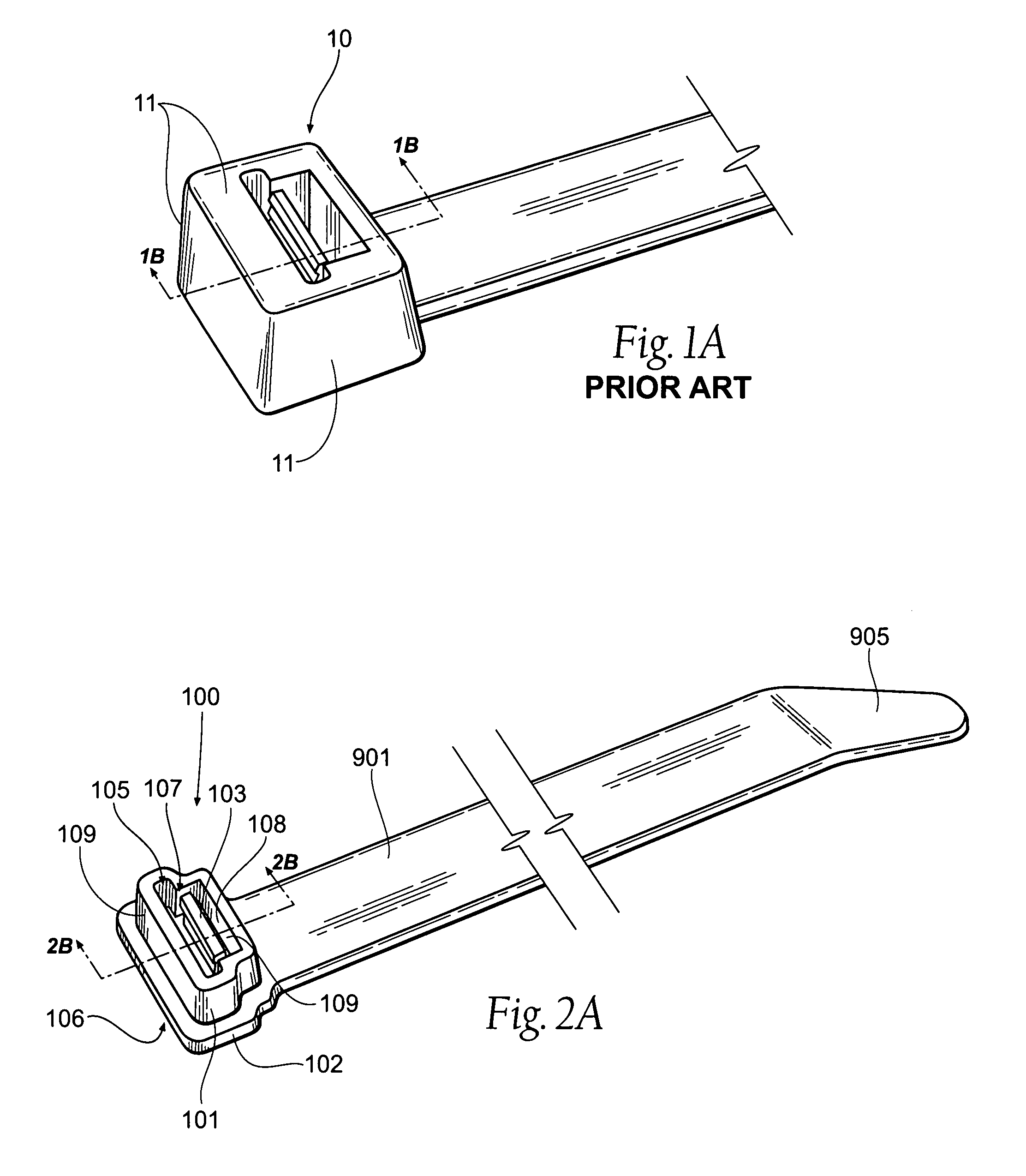
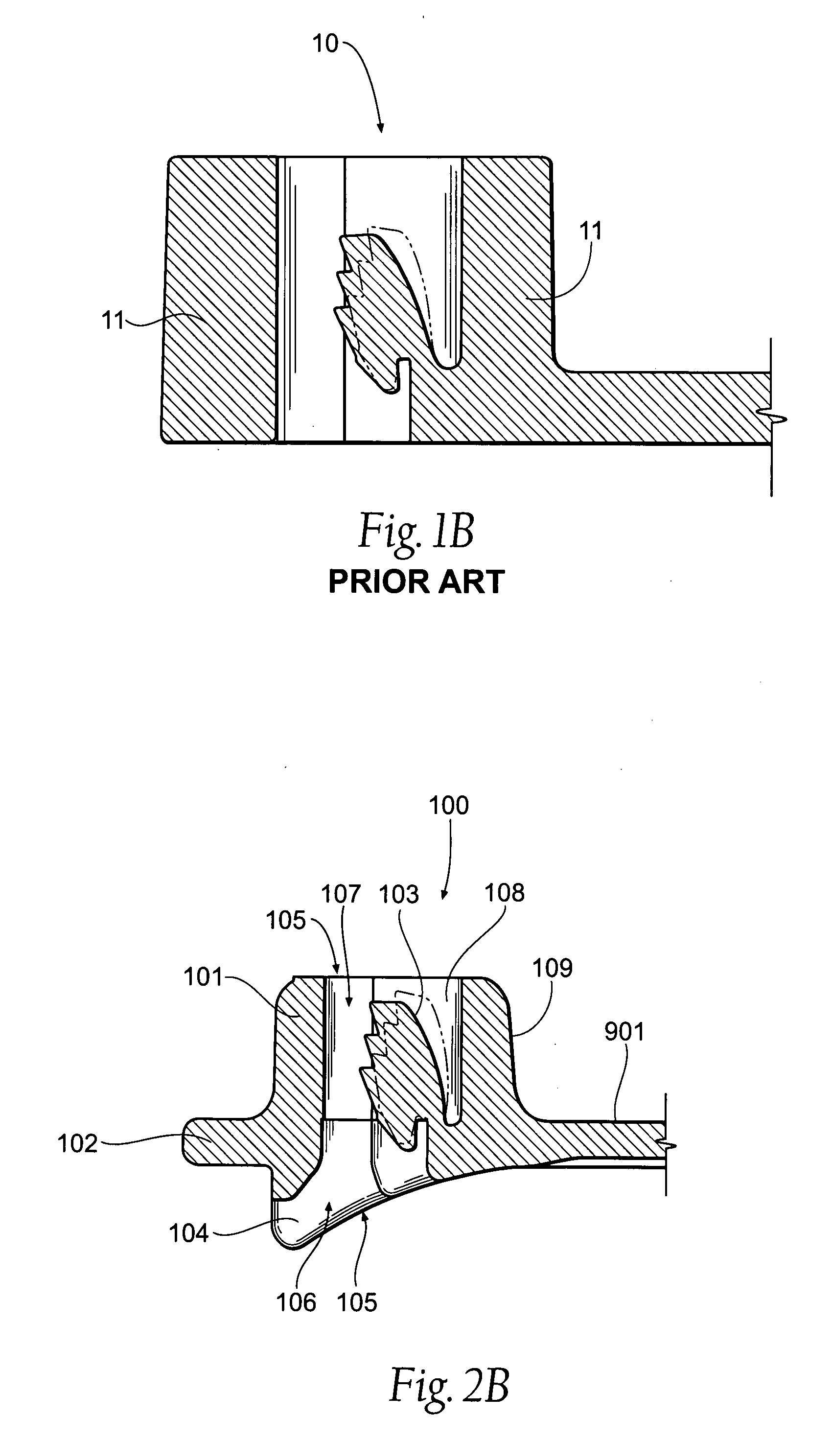
[0054]Referring to FIGS. 1A and 1B, a previous locking tie head 10 is shown. The relative mass of the tie head 10 is especially evident with reference to the solid molded sections 11. As previously described, such bulk adds cost in both raw material and processing time.

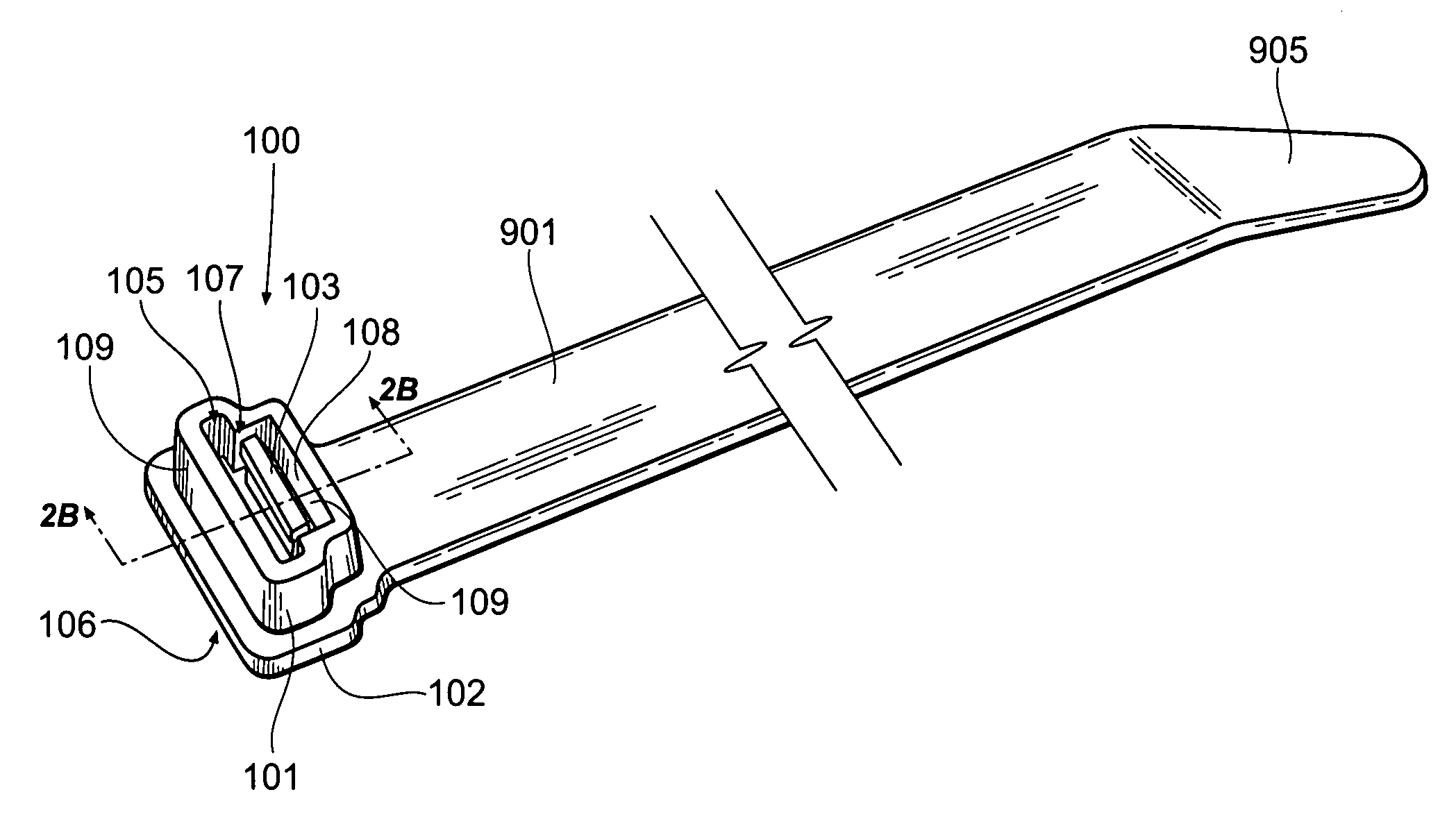
[0055]Referring to FIGS. 2A-D, a first embodiment of the invention includes a tie head 100 having a wall 101, a reinforcement rib 102, and a pawl 103. The wall 101 has a reduced cross section, an outer wall surface 109 and an inner wall surface 108, which circumferentially forms an opening 105 having an entrance 106 and an exit 107. Generally, the reinforcement rib 102 is attached to, or disposed on, the wall 101 outer surface 109, and the pawl 103 is attached to the wall 101 inner surface 108 and is disposed at least partially in the opening 105 adapted to receive a free end 905 of a retaining strap 901. More specifically referring to FIG. 2B, the reinforcement rib 102 preferably encircles the wall 101, is preferably...


PUM


Abstract

A low profile locking tie head having a reduced wall thickness is provided for use in conjunction with a flexible strap. The low profile head comprises a wall, which circumferentially defines an opening, a reinforcement rib attached to the wall, and a pawl mechanism disposed at least partially inside the opening. A pair of clamping rails preferably provides a complete clamping surface, lowers the required tie head height, and assists in the transfer of force to the reinforcement rib. Further, a tie head retainer is provided to allow secure connection to a predetermined support structure.

Description

RELATED APPLICATIONS [0001]This application claims the benefit of U.S. Design patent application Ser. No. 29 / 263,127, filed 17 Jul. 2006, which is a continuation of U.S. Design patent application Ser. No. 29 / 216,331, filed 1 Nov. 2004.BACKGROUND OF THE INVENTION [0002]This invention relates to flexible ties and, more particularly, to a normal entry low profile locking tie head having a reduced cross-section sidewall thickness for use with a flexible tie.[0003]Flexible ties for use in bundling elongated members such as wires, cables, etc. are well known. Typically, such ties include an elongated flexible strap made of suitable material. The tie usually has a free end (tail) and a locking head at the opposite end. The strap is flexible; the free end (tail) is capable of being looped 270 degrees around back toward itself and inserted into the locking head after which the diameter of the loop formed by the strap can be adjusted to fit in the desired manner over the intended bundle.[0004...

Claims


Application Information

Patent Timeline
Patent Type & Authority Applications(United States)
IPC IPC(8): B65D63/00
CPCF16L3/2332Y10T24/14Y10T24/4072Y10T24/1498
Inventor GEIGER, GERARD G.
Owner HELLERMANNTYTON CORP
Why Eureka
Try Eureka