Hurricane panel clip and hook

a technology for hurricane panels and hooks, applied in the direction of hurricane panels/movable grilles, screws, building repairs, etc., can solve problems such as damage to structures, and achieve the effects of reducing time and effort, eliminating ladder climbing, and less time for hurricane panels

Inactive Publication Date: 2008-08-14
VUSAFE IND
View PDF9 Cites 1 Cited by
  • Summary
  • Abstract
  • Description
  • Claims
  • Application Information

AI Technical Summary

Benefits of technology

[0014]The hook is attached to the structure or to a header that is attached to the structure. The hook has an angled section that is meant to engage a groove with a matched angled surface in the clip. The groove with the angled surface may be entirely formed in the clip or formed by the clip and the panel. The clip is attached to the top of the panel by, in illustrative embodiments by a stud and nut or by a bolt through the panel into a tapped hole in the clip body, or by a bolt through the clip body and panel into a nut. The arrangement allows the panel to be pulled down so that the hook and clip are fully engaged. The bottom of the panel is secured to a track or other such fixture or the building structure by bolts or screws. The bottom of the panel is secured such that the top hook and clip will not become disengaged. This process has demonstrated as much a 60% less time to install hurricane panels while eliminating climbing of a ladder. In an emergency, e.g. an approaching hurricane, the reduced time and effort to install hurricane panels according to the present invention could be critical to protection of property, livelihood and personal safety. The present invention advantageously saves time and improves safety of installing such panels.
[0015]In one illustrative embodiment the panel may be attached by an installer with access only to the bottom of the panel. The top of the panel is inserted into the header above the hook. The panel is then straightened vertically and pulled down engaging the hook and clip. The bottom of the panel is then secured to the structure. A lateral center support may be used if the panel is long, and the panels may be overlapped to increase strength.

Problems solved by technology

Hurricanes, typhoons and cyclones all have high winds that can destroy structures due to the force of the wind alone, but also due to debris that impact property and humans.
However, the art disclosed in this patent also requires the installer to take the time to climb a ladder to reach and screw tight the panels.

Method used


Image

  • Hurricane panel clip and hook
  • Hurricane panel clip and hook
  • Hurricane panel clip and hook

Examples


Embodiment Construction

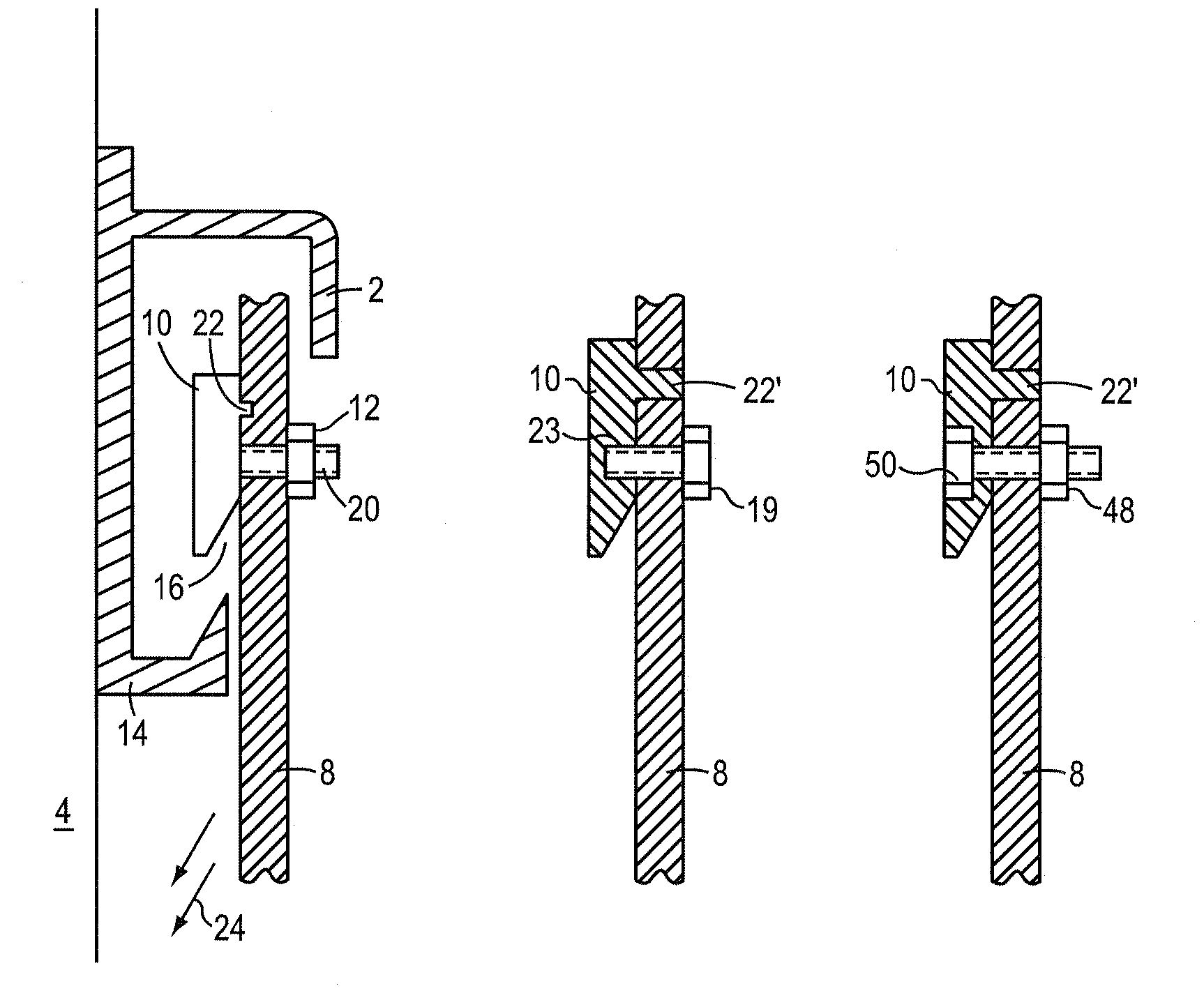
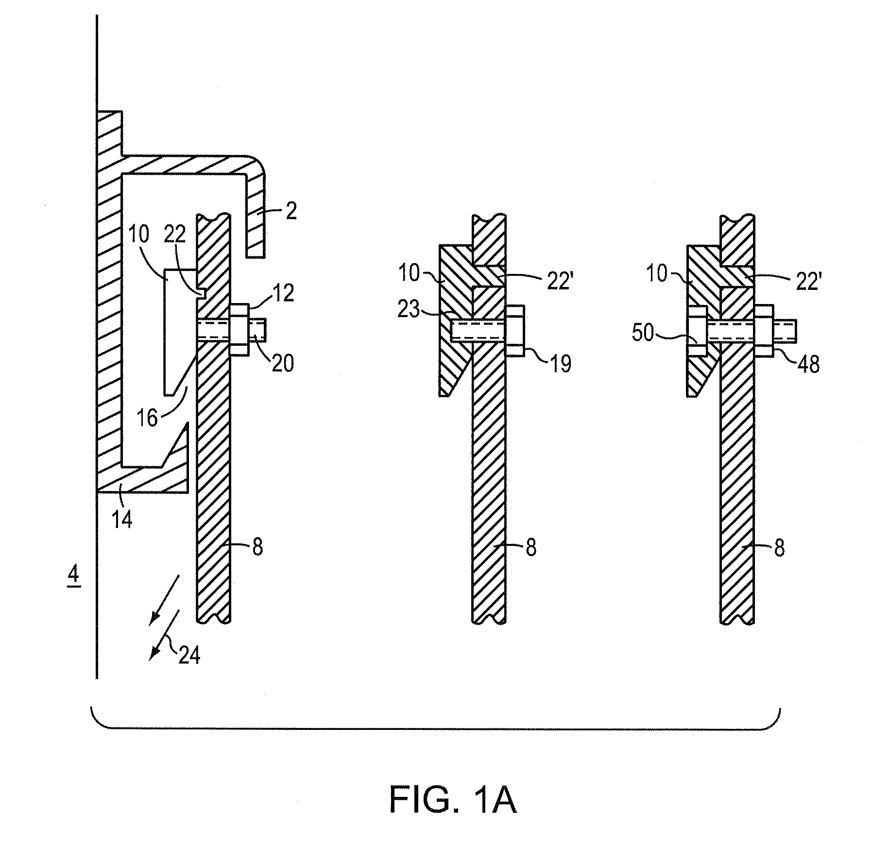
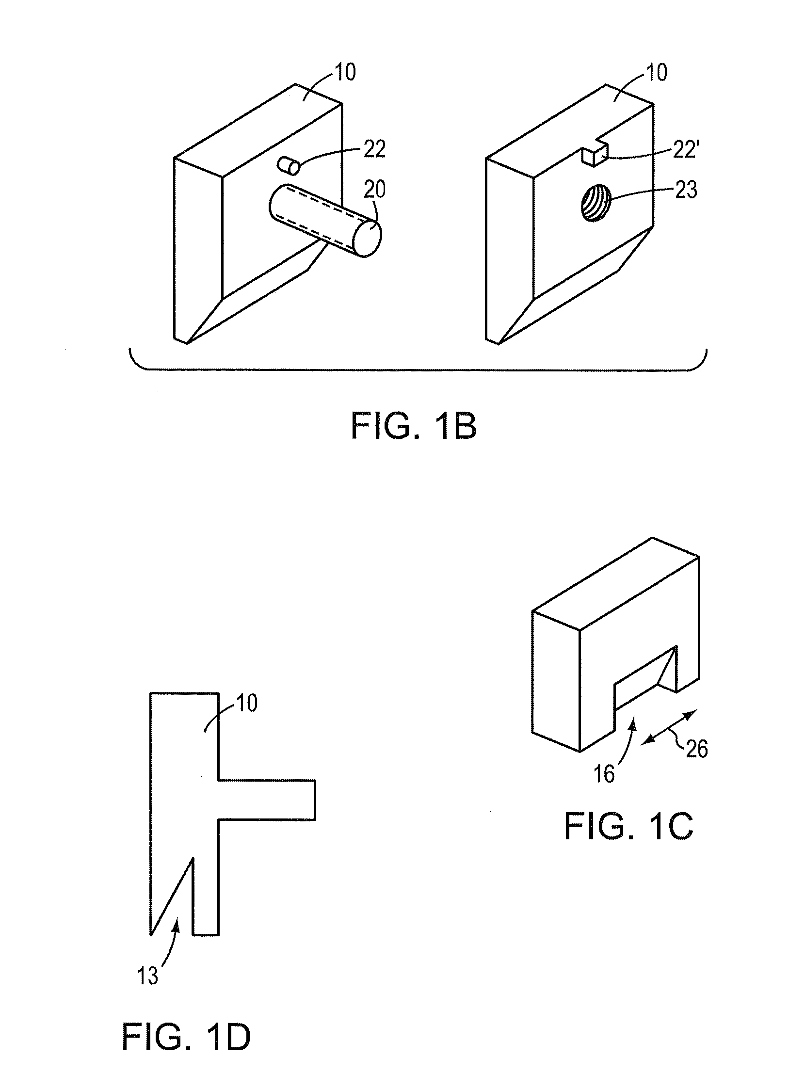
[0027]FIG. 1A is a cutaway view of a protective panel 8 with a clip 10 with a threaded extension 20 suitable for mating to a nut 12. The nut 12 secures the clip 10 to the corrugated panel 8. In this illustration an anti-rotation nib 22 extends from the clip 10 into a mating recess or notch just above where the threaded extension traverses the panel, but an aperture or through hole in the panel may replace the recess.

[0028]An “h” shaped header 2 is attached to the structure 4, in this case with a screw 6. Other screws (not shown) may be used to better secure the header to the structure 4. In one illustrative example, the “h” extends about 2.72″ from the structure and is made of 6063-T6 aluminum and may be of various lengths.

[0029]At the lower end of the header a hook 14 is formed that mates with a groove 16 formed between the clip 10 and the panel 8. In operation the clip is hoisted above the hook 14 and then pulled down in the directions of the arrow 24. The clip groove 16 is seated...


PUM


Abstract

A mounting for a protective panel to a structure that provides a block with an angled surface that forms a lateral groove facing downward that is attached to the top of the panel. A hook is attached to the structure with an upward facing angled surface that matches the downward facing lateral groove of the clip. The panel is raised to where the clip is above the hook and then pulled down so that the groove and the hook mate securing the panel to the structure. There is no need for an installer to climb to the top of the panel. The lower end of the panel may be secured to the structure by standard methods including screwing directly to the structure. The panel may also include lateral center supports to prevent the panels from bending during high winds.

Description

CROSS-REFERENCE TO RELATED APPLICATIONS[0001]The present application claims the benefit of U.S. Provisional Patent Application Ser. No. 60 / 889,372, filed on Feb. 12, 2007, which provisional application is entitled: “Hurricane Panel Clip and Channel,” and is of common inventorship, and which provisional application is hereby incorporated herein by reference. The present application is also related to a co-filed application titled, Hurricane Panel Hook, of common ownership, inventorship, and which application is hereby incorporated herein by references.BACKGROUND OF THE INVENTION[0002]1. Field of the Invention[0003]The present invention relates to the protection of windows, doors and other vulnerable locations from damage due to wind and windborne debris.[0004]2. Background Information[0005]Hurricanes, typhoons and cyclones all have high winds that can destroy structures due to the force of the wind alone, but also due to debris that impact property and humans.[0006]Some building code...

Claims


Application Information

Patent Timeline
Patent Type & Authority Applications(United States)
IPC IPC(8): E04G17/00E04B1/38F16B39/00
CPCE06B9/02E04H9/14Y02A50/00
Inventor CRAIG, PAUL M.BODENSIEK, PAUL
Owner VUSAFE IND
Why Eureka
Try Eureka