Rack and pinion steering apparatus having rack bearing wear compensation with damping

a technology of damping and bearings, which is applied in the direction of gearing, shock absorption devices, hoisting equipments, etc., can solve the problems of not being able to adjust, the yoke does not allow rack adjustment, and the bearing support is not adjustable, so as to prevent over-tightening and slow down the reaction of the adjustment mechanism

Active Publication Date: 2008-08-14
STEERING SOLUTIONS IP HLDG +1
View PDF18 Cites 19 Cited by
  • Summary
  • Abstract
  • Description
  • Claims
  • Application Information

AI Technical Summary

Benefits of technology

[0010]Accordingly, the subject invention provides a rack and pinion steering apparatus having an adjustment mechanism to adjust the position of the rack relative to the pinion, thereby compensating for wear between the rack and the

Problems solved by technology

Since the yoke is staked into position the yoke and bearing support is not adjustable after the complete installation of the yoke into the assembly.
Therefore the yoke does not allow for adjustment of the rack after the completed assembly of a vehicle, and further provides no adjustment during the operation of the power steering assembly.
The teeth on the rack, the teeth on the pinion, the housing and the bearing

Method used


Image

  • Rack and pinion steering apparatus having rack bearing wear compensation with damping
  • Rack and pinion steering apparatus having rack bearing wear compensation with damping
  • Rack and pinion steering apparatus having rack bearing wear compensation with damping

Examples


Embodiment Construction

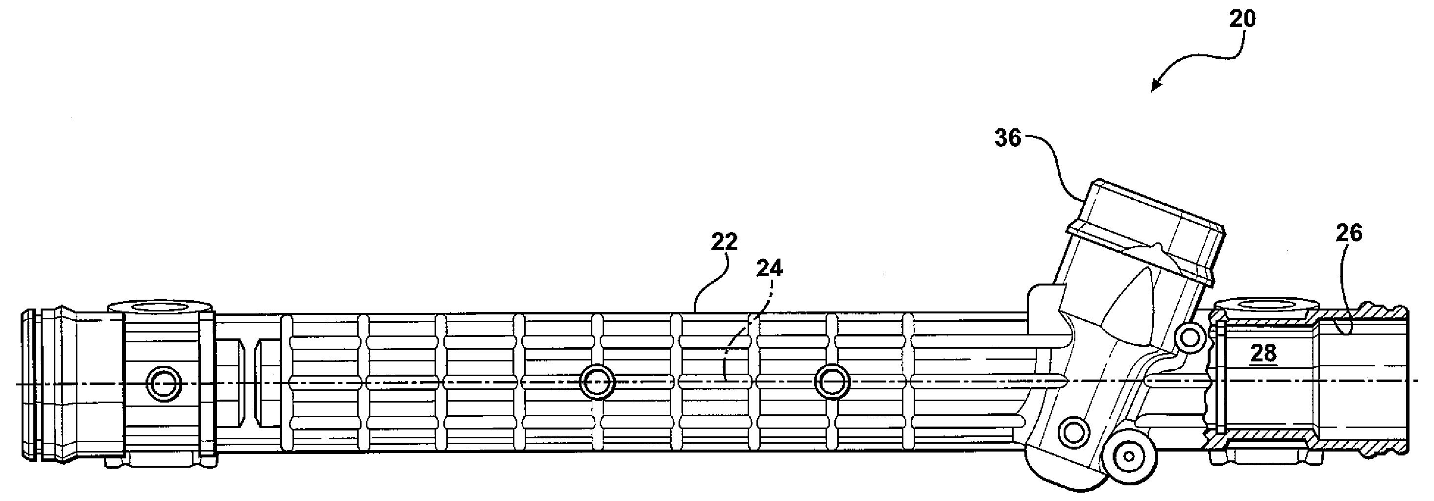
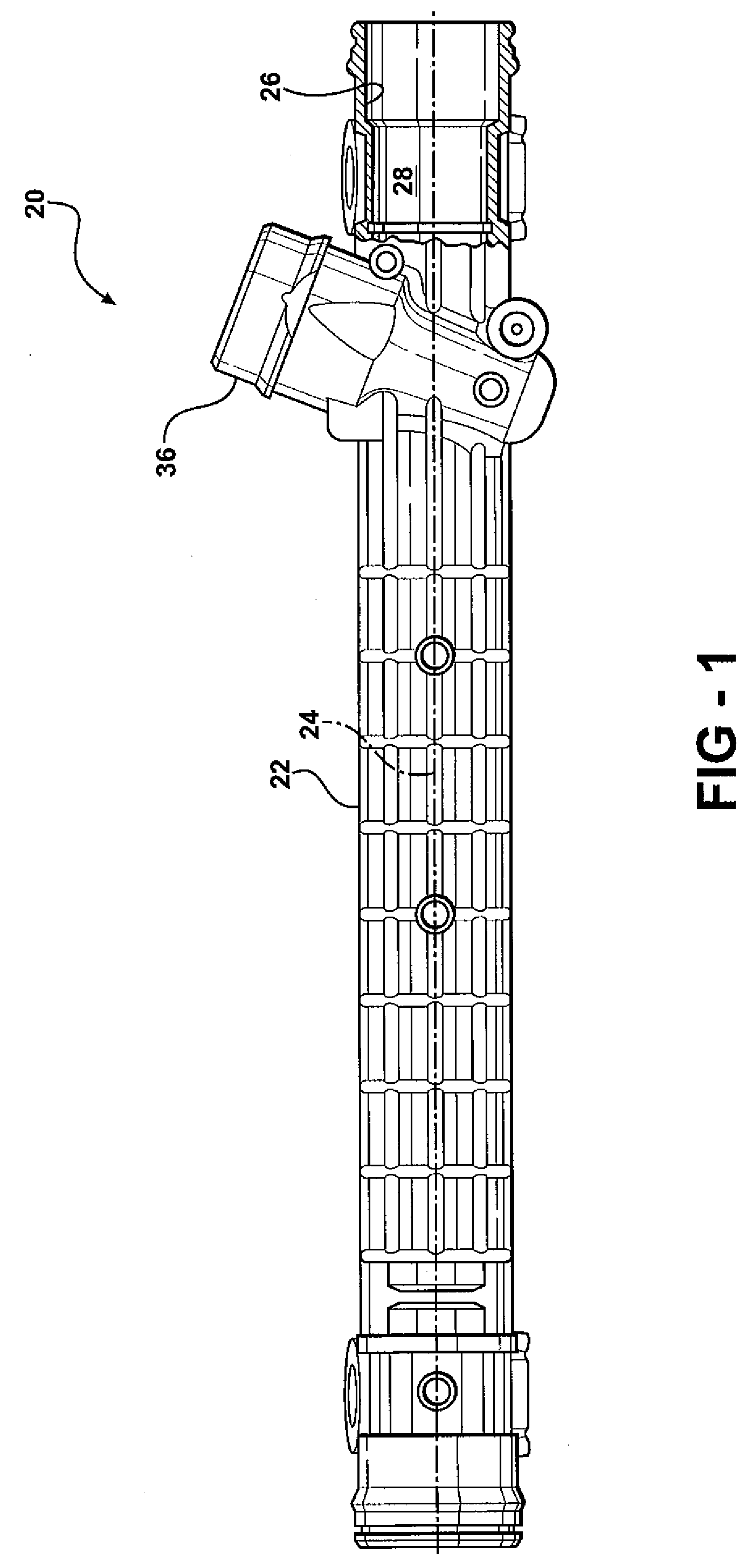
[0019]Referring to FIGS. 1 through 4, wherein like numerals indicate corresponding parts throughout the several views, a first embodiment of a power steering apparatus is generally shown at 20.

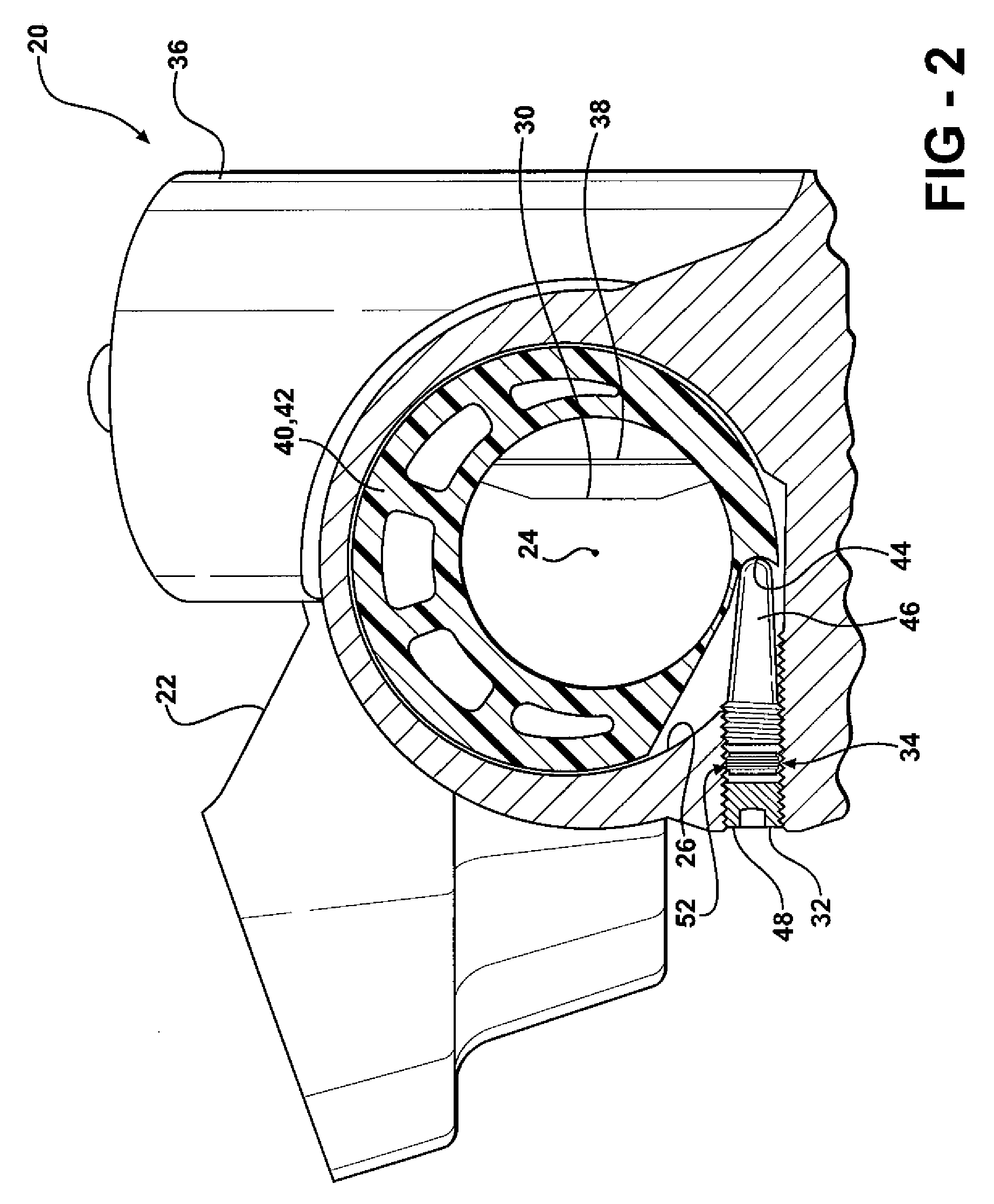
[0020]Referring to FIGS. 1 and 2, the first embodiment of the power steering apparatus includes a housing 22, with the housing 22 defining a chamber 26. The chamber 26 includes an inner surface 28. A gear system 29 is supported by the housing 22. The gear system 29 includes a first gear 30 and a second gear 38. The first gear 30 and the second gear 38 are in meshing engagement with each other.

[0021]As described and shown herein, the gear system 29 includes a rack and pinion gear system 29. However, it should be appreciated that the gear system 29 may include other types and configurations of gear systems 29, with the housing being configured to support and accommodate the specific type of gear system 29 utilized. As shown and described herein, the first gear 30 includes a rack 30. Accordingly,...


PUM


Abstract

A power steering apparatus includes a housing defining a chamber. A rack is disposed within the chamber and is moveable along a longitudinal axis. A pinion extends into the chamber for meshing engagement with the rack. A bearing supports the rack relative to the housing and is moveable relative to the housing to re-position the rack relative to the pinion. An adjustment mechanism continuously biases the bearing in response to loosening of the meshing engagement to re-position the rack. A dampener resists the movement of the bearing to slow the re-positioning of the bearing. Preferably, the dampener includes a plastic fluid having a very high viscosity. The plastic fluid is disposed between adjacent moving parts to resist the relative movement between the bearing and the housing.

Description

CROSS REFERENCE TO RELATED APPLICATION[0001]This application is a continuation-in-part of U.S. patent application Ser. No. 11 / 409,111 filed on Apr. 21, 2006, which claims the benefit of U.S. Provisional Patent Application Ser. No. 60 / 695,494 filed on Jun. 30, 2005, the disclosures of each of which are hereby incorporated by reference; and this application also claims the benefit of U.S. Provisional Patent Application Ser. No. 60 / 930,062 filed on May 14, 2007 and U.S. Provisional Patent Application Ser. No. 60 / 931,521 filed on May 24, 2007, the disclosures of each of which are hereby incorporated by reference.BACKGROUND OF THE INVENTION[0002]1. Field of the Invention[0003]The subject invention generally relates to a power steering apparatus for turning steerable wheels on a vehicle.[0004]2. Description of the Prior Art[0005]Power steering systems having a rack and a pinion are utilized in nearly all of today's vehicles to steer at least two of the wheels of a vehicle. The steering wh...

Claims


Application Information

Patent Timeline
IPC IPC(8): B62D5/00
CPCB62D3/12B62D3/123Y10T74/19623F16H2055/281Y10T74/1967F16H55/283
Inventor DODAK, TONY M.CHAMPAGNE, ANTHONY J.EICKHOLT, MICHAEL A.ARLT, GEORGE E.
Owner STEERING SOLUTIONS IP HLDG
Why Eureka
Try Eureka