
Movable body driving mechanism

Active Publication Date: 2008-08-14
PANASONIC CORP
View PDF3 Cites 12 Cited by
  • Summary
  • Abstract
  • Description
  • Claims
  • Application Information

AI Technical Summary

Benefits of technology

[0007]It is an object of the present invention to provide a movable body driving mechanism whose simple configuration achieves cam driving without looseness and allows easy manufacturing.
[0009]In accordance with the present invention, a lateral surface of the cam follower can be made to contact a lateral surface of the cam groove constantly, thus achieving the cam driving without looseness. Also, since the biasing means or the like is not needed, it is possible both to simplify the configuration and to reduce the number of manufacturing steps.

Problems solved by technology

However, since the configuration disclosed in JP 5(1993)-29013 U requires the biasing means, the number of manufacturing steps increases inevitably.

Method used


Image

  • Movable body driving mechanism
  • Movable body driving mechanism
  • Movable body driving mechanism

Examples


embodiment

[0023][1. Configuration of the Imaging Apparatus]

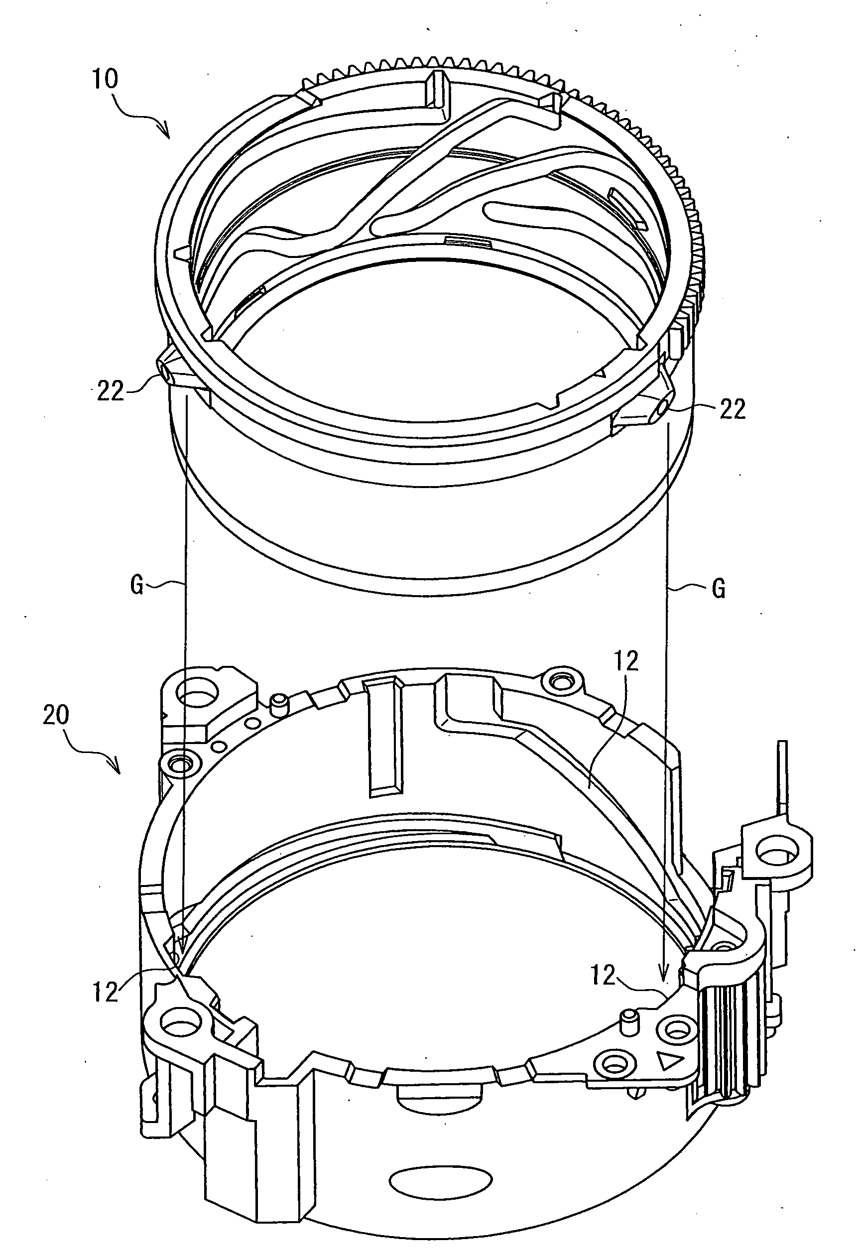
[0024]FIG. 1 illustrates an example of an apparatus including a movable body driving mechanism in the present embodiment. The apparatus shown in FIG. 1 is an imaging apparatus mounted in a digital camera. An imaging apparatus 1 includes various lenses such as a zoom lens and a focus lens, an imaging device that converts incident light into an electric signal and outputs this signal, etc. It should be noted that the imaging apparatus illustrated in the present embodiment merely is an example and can be mounted in not only the digital camera but also a video camera or the like.

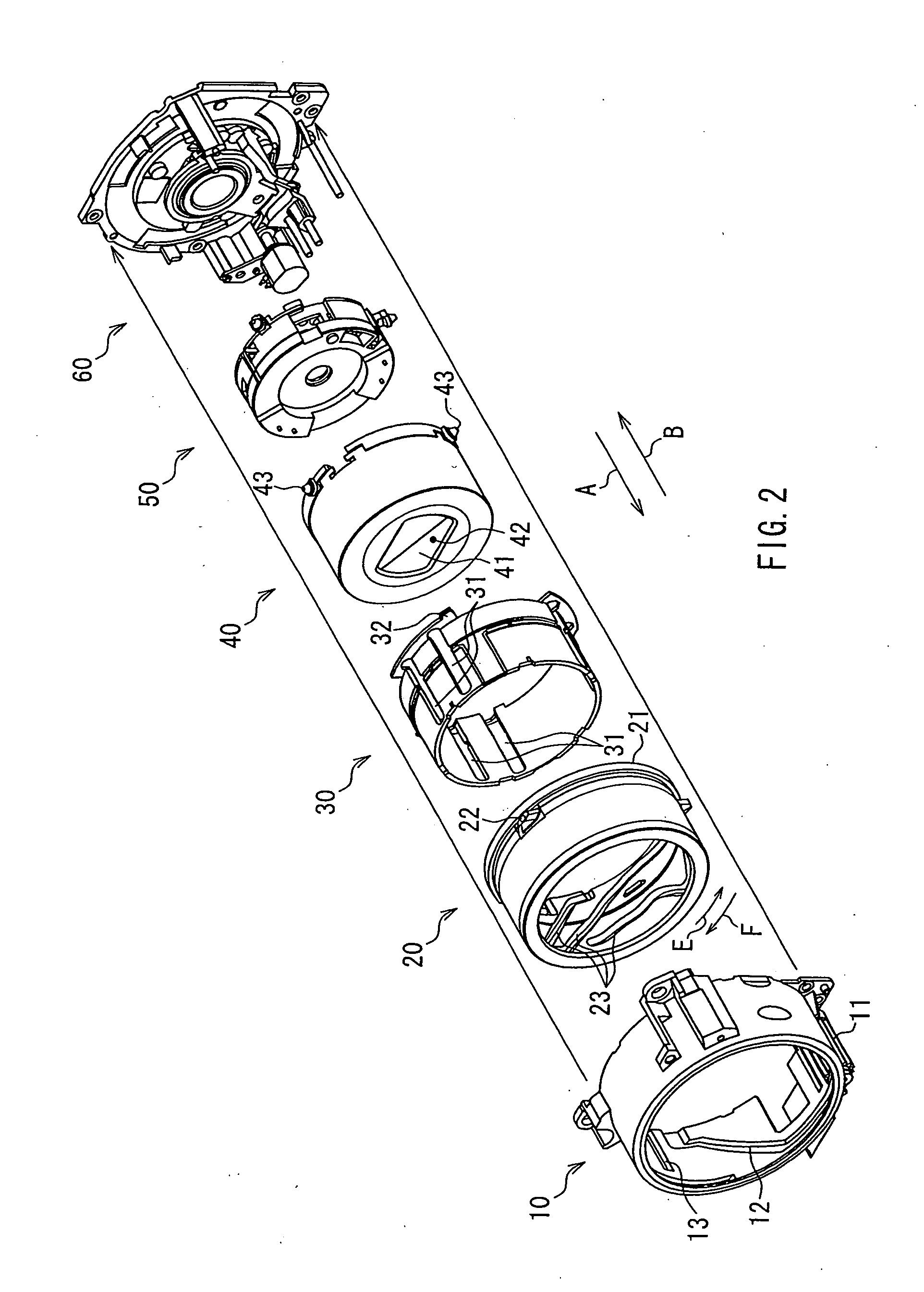
[0025]In the imaging apparatus 1, a fixed frame 10, a drive frame 20 and a first group unit 40 are arranged at coaxial positions. Further, a gear 11 is disposed near the fixed frame 10. The gear 11 is driven rotationally by a driving means such as a motor. The drive frame 20 and the first group unit 40 are configured to be moved in a direction indicated by an arro...


PUM


Abstract

The present invention is directed to a movable body driving mechanism including a first frame and a second frame that is capable of moving relative to the first frame. The movable body driving mechanism includes a cam groove that is formed in the first frame, and a cam follower that is formed in the second frame and inserted movably in the cam groove. The cam groove includes a plurality of regions having different widths. The cam follower is formed to have a shape with a plurality of outer diameters, and different parts of the cam follower contact an inner lateral surface of the cam groove in each of the plurality of regions. With this configuration, the lateral surface of the cam follower can be made to contact the lateral surface of the cam groove constantly, thus achieving the cam driving without looseness. Also, since the biasing means or the like is not needed, it is possible both to simplify the configuration and to reduce the number of manufacturing steps.

Description

BACKGROUND OF THE INVENTION[0001]1. Field of the Invention[0002]The present invention relates to a movable body driving mechanism. In particular, the present invention relates to a movable body driving mechanism capable of expanding and retracting a movable body by cam driving. This movable body driving mechanism is applicable to a lens barrel or the like.[0003]2. Description of Related Art[0004]In recent years, a lens and a barrel mounted in an imaging apparatus such as a digital camera or a video camera can be moved along an optical axis direction by a cam mechanism formed in the barrel. In such an imaging apparatus, in order to obtain a high quality optical image, it is necessary to move the lens with high accuracy and restrict the lens position.[0005]JP 5(1993)-29013 U discloses a configuration including a biasing means for biasing a cam follower toward a cam groove, in which a tip portion of the cam follower is made to contact an inclined surface of the cam groove constantly, t...

Claims


Application Information

Patent Timeline
IPC IPC(8): F16H35/08
CPCG02B7/08Y10T74/1683G03B11/04G02B7/102G03B11/043
Inventor KUWAHARA, TAKUMIFUJINAKA, HIROYASU
Owner PANASONIC CORP
Features
  • Generate Ideas
  • Intellectual Property
  • Life Sciences
  • Materials
  • Tech Scout
  • Unparalleled Data Quality
  • Higher Quality Content
  • 60% Fewer Hallucinations
Learn More