Electrical current source, in particular welding current source

a current source and electrical technology, applied in the field of electrical current sources, can solve the problems of an undetectable high degree of control, and achieve the effect of high synchronization

Inactive Publication Date: 2008-08-14
LORCH SCHWEISSTECHNIK GMBH
View PDF10 Cites 39 Cited by
  • Summary
  • Abstract
  • Description
  • Claims
  • Application Information

AI Technical Summary

Benefits of technology

[0012]It is therefore readily possible to clock the bridge circuits of the resonant converters which are connected in parallel in a completely synchronous manner, with the result that, even for a very large number of parallel resonant converters, only the same amount of outlay on control is required as for a single resonant converter.

Problems solved by technology

This is equivalent to an undesirably high degree of outlay on control.

Method used


Image

  • Electrical current source, in particular welding current source
  • Electrical current source, in particular welding current source
  • Electrical current source, in particular welding current source

Examples


Embodiment Construction

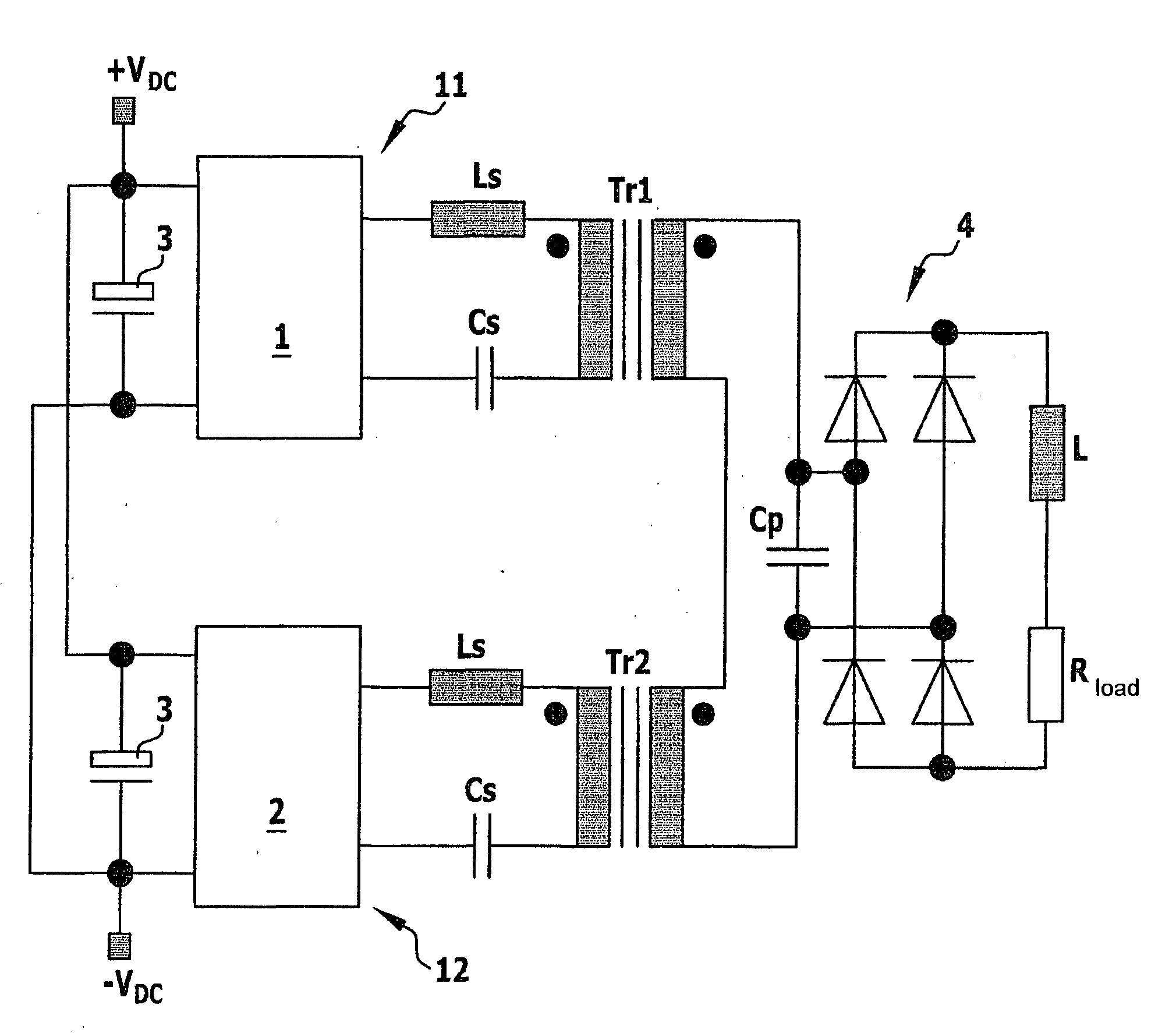
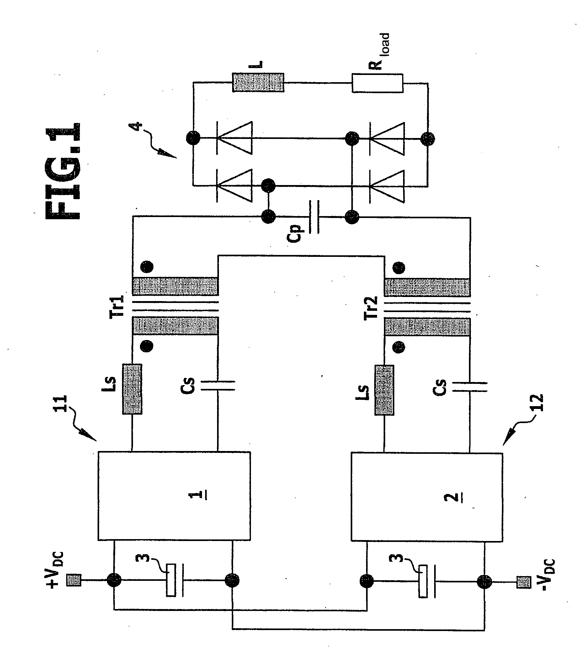
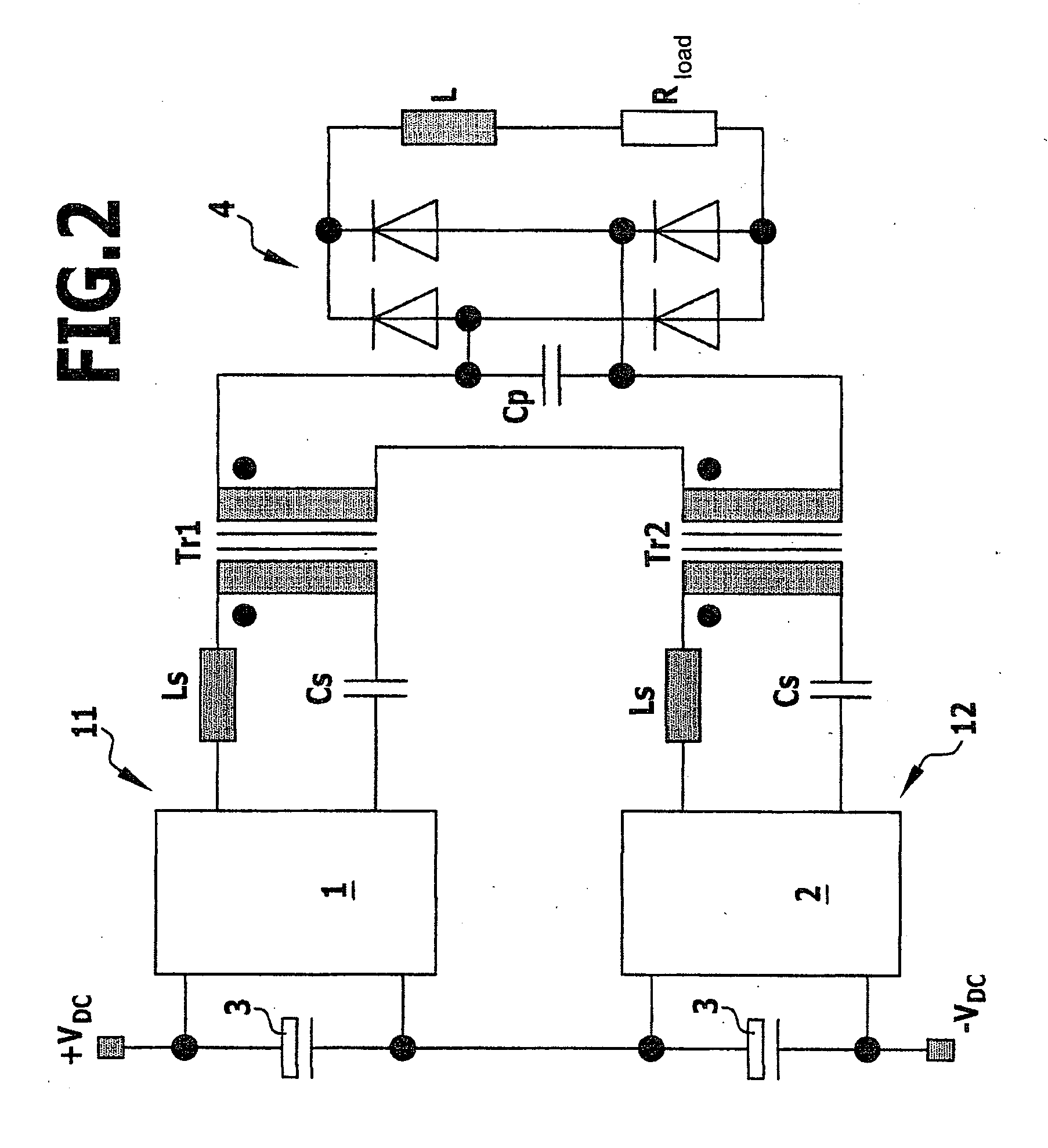
[0026]According to FIG. 1, two resonant converters 11 and 12 which are connected in parallel with one another are connected to the output contacts +VDC and −VDC. Each resonant converter 11 and 12 has, at the input end, a clocked bridge circuit 1 or 2 which converts the input-end direct electrical voltage of the direct-current source into an output-end alternating electrical voltage whose frequency corresponds to the clock frequency. In order to prevent alternating electrical currents or voltages from being able to be coupled back to the input end of the bridge circuits 1 and 2, the inputs of the two bridge circuits 1 and 2 are in each case connected to one another via capacitors 3 with a high capacitance, for example via electrolytic capacitors.

[0027]Series circuits which comprise an inductance Ls, the primary side of a high-frequency transformer Tr1 or Tr2 and a series capacitance Cs are in each case disposed between the outputs of the bridge circuits 1 and 2. The secondary sides o...


PUM

PropertyMeasurementUnit
capacitanceaaaaaaaaaa
series capacitanceaaaaaaaaaa
currentaaaaaaaaaa

Abstract

According to the invention, parallel resonant converters which are or can be connected to a load circuit via a transformer in each case are provided with a common series circuit of the secondary sides of the transformers. Therefore, despite variation of the frequency-determining components, it is possible for all the resonant converters to supply an output-side load circuit with approximately identical powers when the bridge circuits of the resonant converters are clocked in a synchronous manner.

Description

[0001]This application is a continuation of international application number PCT / EP2006 / 064846 filed on Jul. 31, 2006.[0002]The present disclosure relates to the subject matter disclosed in international application number PCT / EP2006 / 064846 of Jul. 31, 2006 and German application number 10 2005 036 806.9 of Aug. 2, 2005, which are incorporated herein by reference in their entirety and for all purposes.BACKGROUND OF THE INVENTION[0003]The invention relates to an electrical current source, in particular a welding current source, having the features of the preamble of Patent Claim 1.[0004]EP 1 251 991 B1 describes a welding current source with a resonant converter which has a bridge circuit which at the input end is connected to a direct-current source. The bridge circuit is in the form of a full bridge. At the output end, the bridge circuit is connected to a resonant circuit whose outputs are connected directly to the load circuit.[0005]A further current source with a resonant convert...

Claims


Application Information

Patent Timeline
Patent Type & Authority Applications(United States)
IPC IPC(8): B23K9/10
CPCH02M3/335Y02B70/1433H02M2001/0077Y02B70/10Y02P80/10H02M1/0077
Inventor AIGNER, HUBERT
Owner LORCH SCHWEISSTECHNIK GMBH
Why Eureka
Try Eureka