Paper transport path of image forming apparatus

a technology of image forming apparatus and paper transport path, which is applied in the directions of transportation and packaging, pile separation, printing, etc., can solve the problems of difficult to achieve high-speed print processing, inability to maintain constant spacing between recording papers, and large load on paper transport mechanism

Active Publication Date: 2008-08-14
SHARP KK
View PDF19 Cites 15 Cited by
  • Summary
  • Abstract
  • Description
  • Claims
  • Application Information

AI Technical Summary

Benefits of technology

[0034]In this case, when the distance of spacing between the recording papers being transported successively becomes wider than the prescribed spacing, the distance of spacing between the recording papers can be changed to be shorter by transporting the succeeding recording paper through the short transport path.

Problems solved by technology

In other words, along with increased print processing speeds, there is a necessity to set the transport speed of the recording paper on the upstream side from the registration rollers even faster, and this is a cause of placing much greater loads on paper transport mechanisms.
Furthermore, since it is difficult to achieve high-speed print processing with only higher transport speeds of the recording paper, the distance of the spacing between a preceding recording paper and a succeeding recording paper is being made smaller (see JP 2005-247267A).
However, the distances of spacing between recording papers is not always held constant and may vary.
For example, recording paper is picked up and fed by a pickup roller in a paper feed portion, but due to variation in the extent of slipperiness of the surface of the recording paper, the pickup roller may slip such that the timing by which the recording paper is picked up may be delayed, thereby increasing the distances of spacing between the recording papers.
For this reason, in a case where the distance of spacing between recording papers is set smaller in order to increase the speed of print processing as in JP 2005-247267A, the distance of spacing between recording papers is made even smaller when the succeeding recording paper is pulled up by the preceding recording paper, and there are large shifts in the timings by which the succeeding recording papers reach the registration rollers, such that transport control of the recording paper by the registration rollers is made difficult.

Method used


Image

  • Paper transport path of image forming apparatus
  • Paper transport path of image forming apparatus
  • Paper transport path of image forming apparatus

Examples


Embodiment Construction

[0049]Hereinafter, an embodiment of the present invention is described in detail with reference to the accompanying drawings.

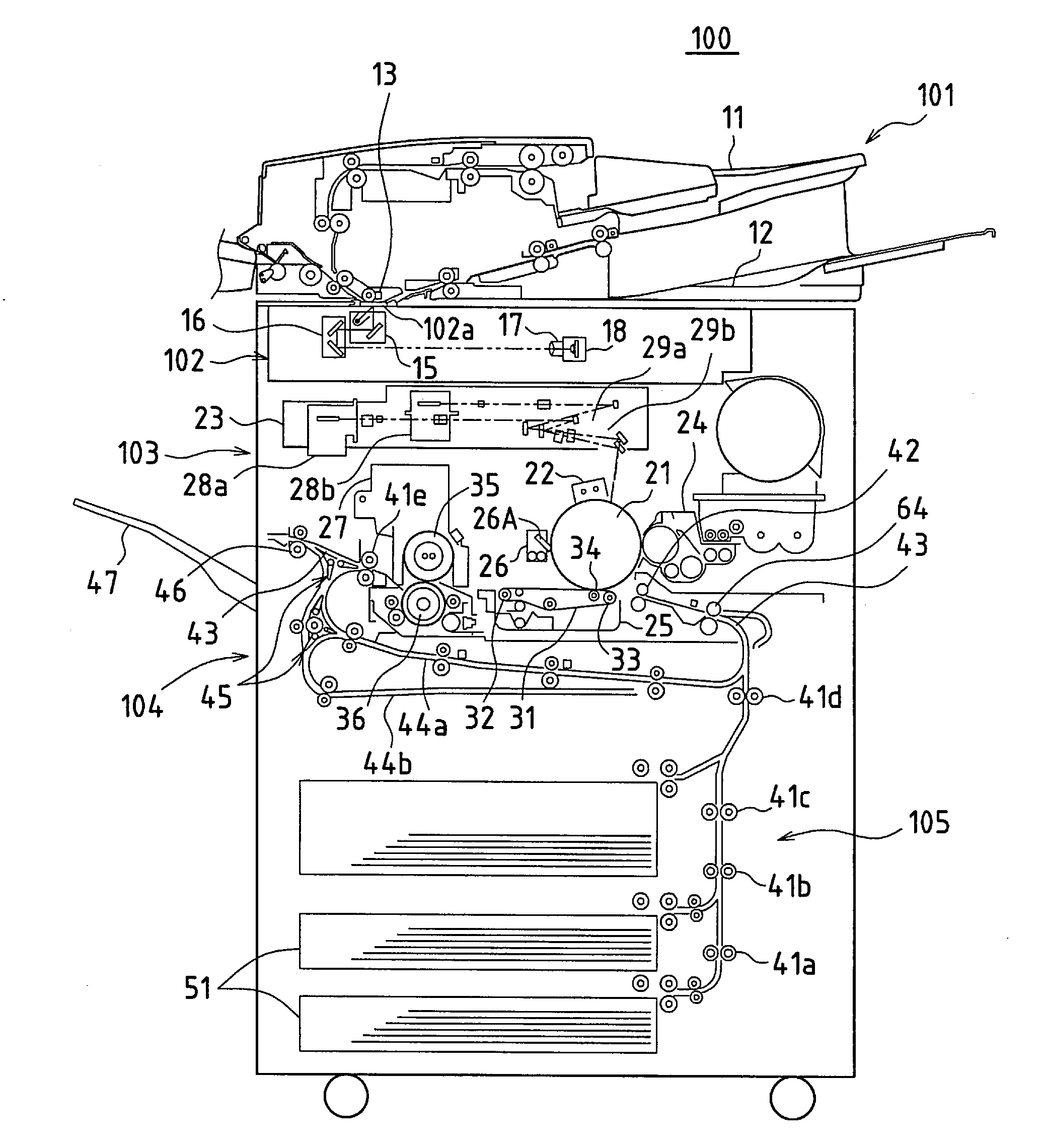
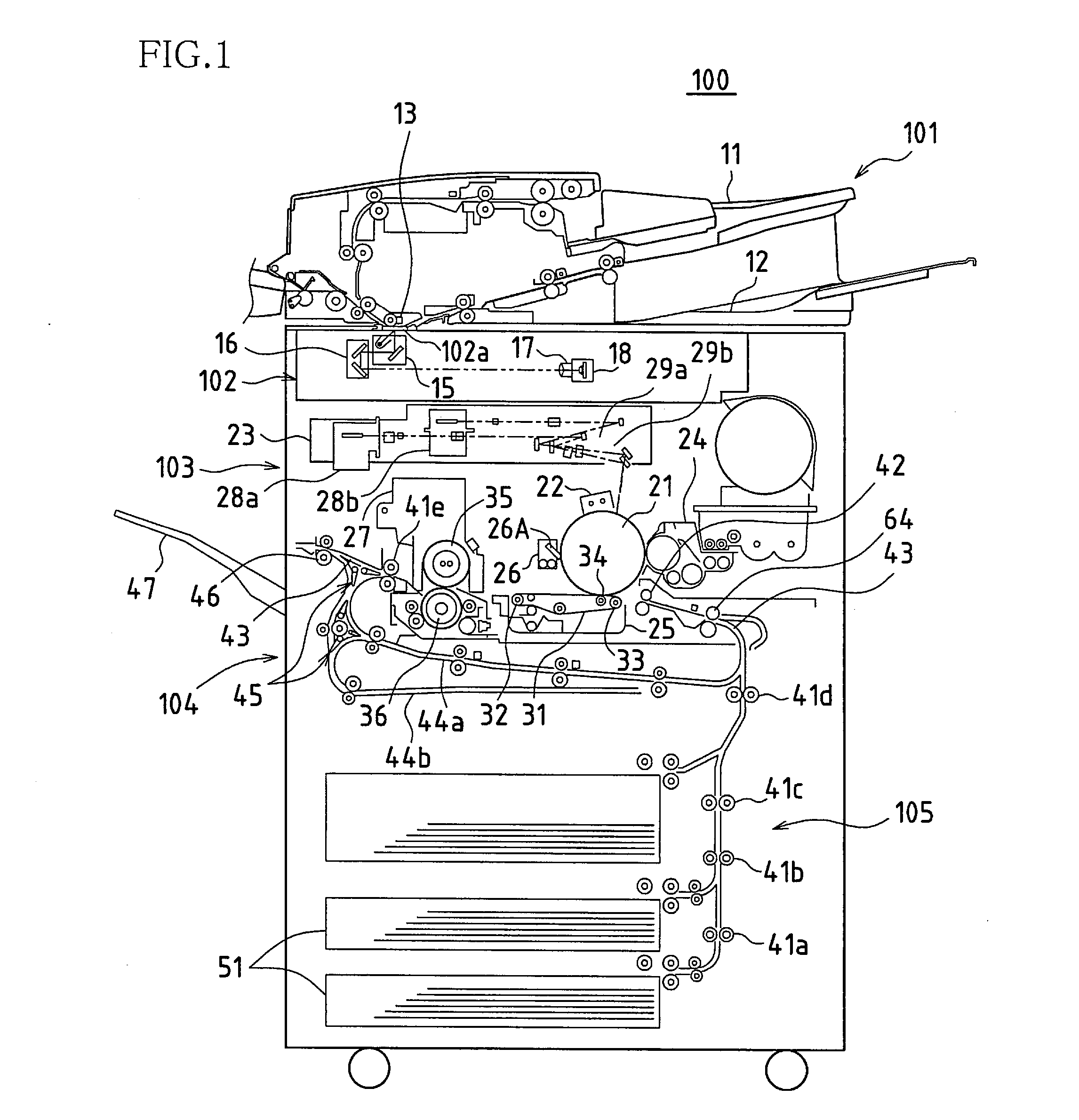
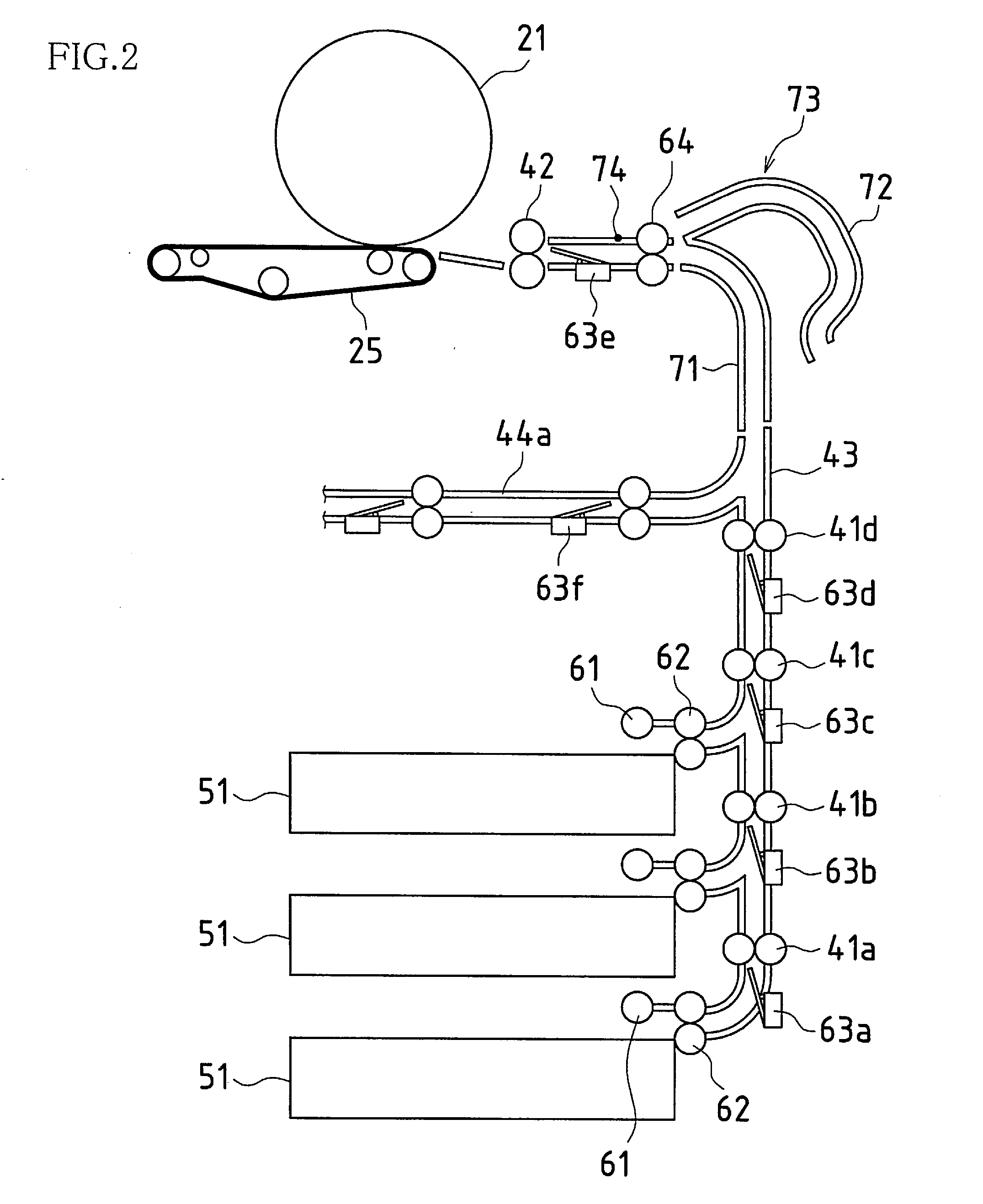
[0050]FIG. 1 is a cross-sectional view showing one embodiment of an image forming apparatus according to the present invention. An image forming apparatus 100 obtains image data that has been read from an original paper or obtains image data that has been received from outside, and forms a monochrome image indicated by the image data on a recording paper, and its structure can be broadly divided into an original paper transport portion (ADF) 101, an image reading portion 102, a print portion 103, a recording paper transport portion 104, and a paper feed portion 105.

[0051]When at least one sheet of an original paper is set in an original setting tray 11 in the original paper transport portion 101, the original paper is picked up and transported from the original setting tray 11 sheet by sheet, and the original paper is guided to and made to pass through an orig...


PUM

PropertyMeasurementUnit
speedaaaaaaaaaa
transport speedaaaaaaaaaa
distanceaaaaaaaaaa

Abstract

A transport path switching unit is provided between transport rollers and pre-registration rollers, and control is performed to switch between a main transport path and an extended transport path of the transport path switching unit such that either the main transport path or the extended transport path is interposed as the part of the paper transport path between the transport rollers and the pre-registration rollers to vary a total length of the paper transport path.

Description

BACKGROUND OF THE INVENTION[0001]This application claims priority under 35 U.S.C. § 119(a) on Patent Application No. 2007-033847 filed in Japan on Feb. 14, 2007, the entire contents of which are herein incorporated by reference.[0002]The present invention relates to image forming apparatuses such as copiers, printers, and facsimile machines, and particularly relates to paper transport paths of image forming apparatuses in which a recording paper is temporarily stopped by registration rollers then transported to a print processing portion.[0003]With this type of image forming apparatus, development has been advancing in recent years toward apparatuses having increased print processing speeds, for example apparatuses have been developed that perform print processing on 100 or more sheets / min. In this regard, along with increased print processing speeds such as these, much greater loads are being placed on paper transport mechanisms.[0004]For example, when carrying out print processing...

Claims


Application Information

Patent Timeline
Patent Type & Authority Applications(United States)
IPC IPC(8): B41F21/00B41F13/00
CPCB65H5/36B65H2301/3331B65H2404/6111B65H2511/11B65H2511/514B65H2513/50B65H2701/1313B65H9/006B65H29/60B65H2220/09B65H2220/02B65H2220/11B65H2220/01
Inventor FUJITA, MASAHIKOTANIGUCHI, TADASUKIMURA, MASAHARUFUKADA, YASUAKIASAKAWA, MASAYATAKAI, YASUHIROKATSURA, NORICHIKAOHISHI, MASATSUGU
Owner SHARP KK
Why Eureka
Try Eureka