Optical diffuser film and light assembly

Inactive Publication Date: 2008-08-14
SKC HAAS DISPLAY FILMS CO LTD
View PDF8 Cites 31 Cited by
  • Summary
  • Abstract
  • Description
  • Claims
  • Application Information

AI Technical Summary

Benefits of technology

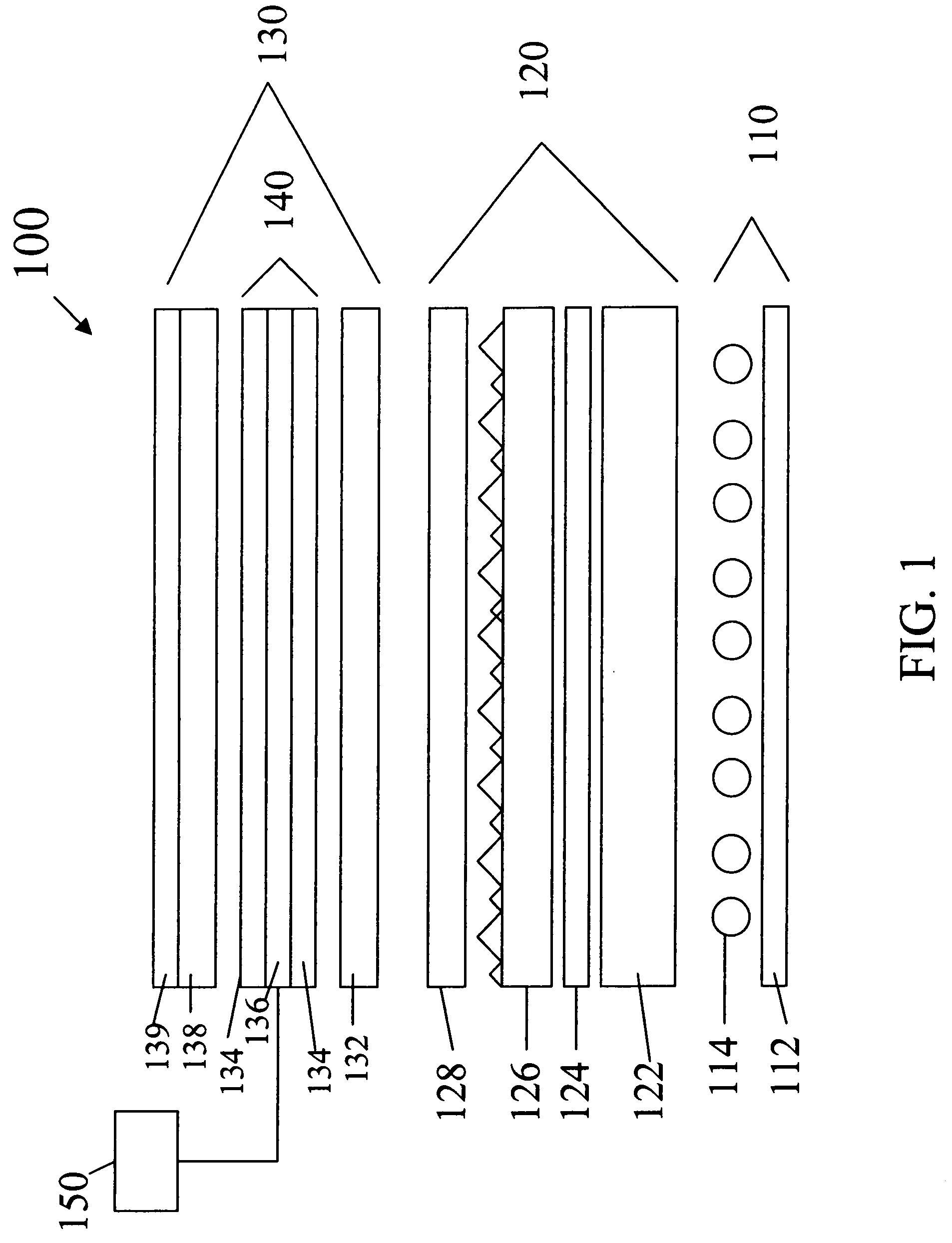
[0008]Another embodiment of the invention is directed to a liquid crystal display (LCD) unit that has a light source and an LCD panel that includes an upper plate, a lower plate, and a liquid crystal layer disposed between the upper and lower plates. The lower plate faces the light source, and includes an absorbing polarizer. An arrangement of light management layers is disposed between the light source and the LCD panel so that the light source illuminates the LCD panel through the arrangement of light management layers. T

Problems solved by technology

Such an illumination profile is not desirable, and so a diffuser plate is used to smooth the illumination profile at the back of the LCD device.
These plates often deform or warp after exposure to the elevated humidity and high temperature caused by the lamps.
In addition, the diffusion plates require customized extrusion compounding to distribute the diffusing particles uniformly throughout the polymer matrix, which further increases costs.
Although this solution is novel the need

Method used


Image

  • Optical diffuser film and light assembly
  • Optical diffuser film and light assembly
  • Optical diffuser film and light assembly

Examples


examples

[0049]Various samples of voided polymeric optical diffuser films were prepared and their performance in combination with an optically transmissive self-supporting substrate was compared to commercially available diffuser films as well as that of the diffuser plate used in a commercially available LCD-TV. The voided polymeric optical diffuser films and optically transmissive self-supporting substrates together were tested for brightness and optical uniformity. The voided polymeric optical diffuser films were tested individually for thermal shrinkage as well. Commercially available foamed or voided films that have been identified as potential diffuser layers were also tested in combination with optically transmissive self-supporting substrates for brightness and optical uniformity and where evaluated as unattached films were tested individually for shrinkage as well.

Sample EX-1

[0050]PET(#7352 from Eastman Chemicals) was dry blended with Polypropylene(“PP”, Huntsman P4G2Z-159) at 22% b...


PUM


Abstract

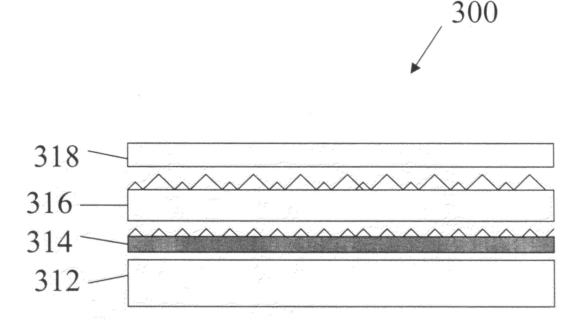
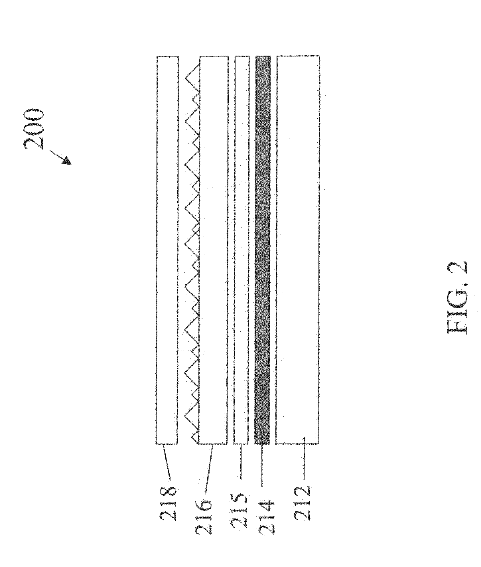
A light assembly comprises a light source, an optically transmissive self- supporting substrate, and coupled with but unattached to the substrate, a voided high Tg semi-crystalline polymeric optical diffuser film that shrinks less than 1% as a result of thermal shrinkage testing.

Description

FIELD OF THE INVENTION[0001]The invention relates to optical displays, and more particularly to liquid crystal displays (LCDs) that may be used in LCD monitors and LCD televisions.BACKGROUND[0002]Liquid crystal displays (LCDs) are optical displays used in devices such as laptop computers, hand-held calculators, digital watches and televisions. Some LCDs include a light source that is located to the side of the display, with a light guide positioned to guide the light from the light source to the back of the LCD panel. Other LCDs, for example some LCD monitors and LCD televisions (LCD-TVs) are directly illuminated using a number of light sources positioned behind the LCD panel. This arrangement is increasingly common with larger displays, because the light power requirements, to achieve a certain level of display brightness, increase with the square of the display size, whereas the available real estate for locating light sources along the side of the display only increases linearly ...

Claims


Application Information

Patent Timeline
IPC IPC(8): G02B5/02
CPCG02B5/0247G02F1/133606G02F1/133604G02B5/0278G02B5/02
Inventor LANEY, THOMAS M.AYLWARD, PETER T.
Owner SKC HAAS DISPLAY FILMS CO LTD
Why Eureka
Try Eureka