
Refurbishable retro-reflective photogrammetric target

Inactive Publication Date: 2008-08-14
HUBBS MACHINE & MFG
View PDF16 Cites 8 Cited by
  • Summary
  • Abstract
  • Description
  • Claims
  • Application Information

AI Technical Summary

Benefits of technology

[0012]The present invention provides a surveying target with a precisely sized and located aperture. The essence of this invention is to provide a means for achieving very close tolerances, within + / −0.0005 inch in the assembly and usage of a retro-reflective photogrammetry as used with close range industrial photogrammetry. The current invention is designed to provide a precisely machined ring that fits into a precisely machined socket of a target body to allow for refurbishing of the retro-reflective dot, or target, by moderately capable personnel in outdoor, rugged, and all weather conditions, while still maintaining the critical X, Y, Z location of the dot, or target, to within + / −0.0005 inch.
[0015]It is, therefore, the principle object of this invention is to provide an improvement in the technology of retro-reflective photogrammetry targets to define an area within + / −0.0005 inch which in turn provides a value tolerance of + / −0.0005 inch that can be refurbished by the average rodman or surveyor in field conditions.
[0016]Another object of this invention is to provide for ready replacement of reflective tape upon the target body without compromising the area, centerline, and offset height tolerances.

Problems solved by technology

Normally, infrared targets without a mask overlay have tolerances within several thousandths of an inch, which may be insufficient to obtain the precision required in a machining operation, in the manufacturing of parts in particular industries, or in industrial surveying.
Though tight tolerances are achieved, much skill, equipment, and time are expended in doing so.
Over time and with usage in field conditions, the retro-reflective tape wears or becomes damaged and its reflectivity diminishes.
Replacing the tape and any overlays on critical targeting in the field jeopardizes the tolerances of any targets.
As a result, the components of the standard materials without a mask overlay make it impossible to meet the tolerances required.
The height tolerance for the target is 0.005 inch which does not meet the needs of industry.
The difficulty of manufacturing multiple components with very close tolerances is that variations or tolerances stack up, or accumulate, during assembly of a target which jeopardizes the goal of a final target at a location within a 0.0005 inch or less tolerance.
Further, the replacement of retro-reflective tape requires skilled labor and equipment in a factory setting unlike the prompt repairs often demanded in the field.

Method used


Image

  • Refurbishable retro-reflective photogrammetric target
  • Refurbishable retro-reflective photogrammetric target
  • Refurbishable retro-reflective photogrammetric target

Examples


Embodiment Construction

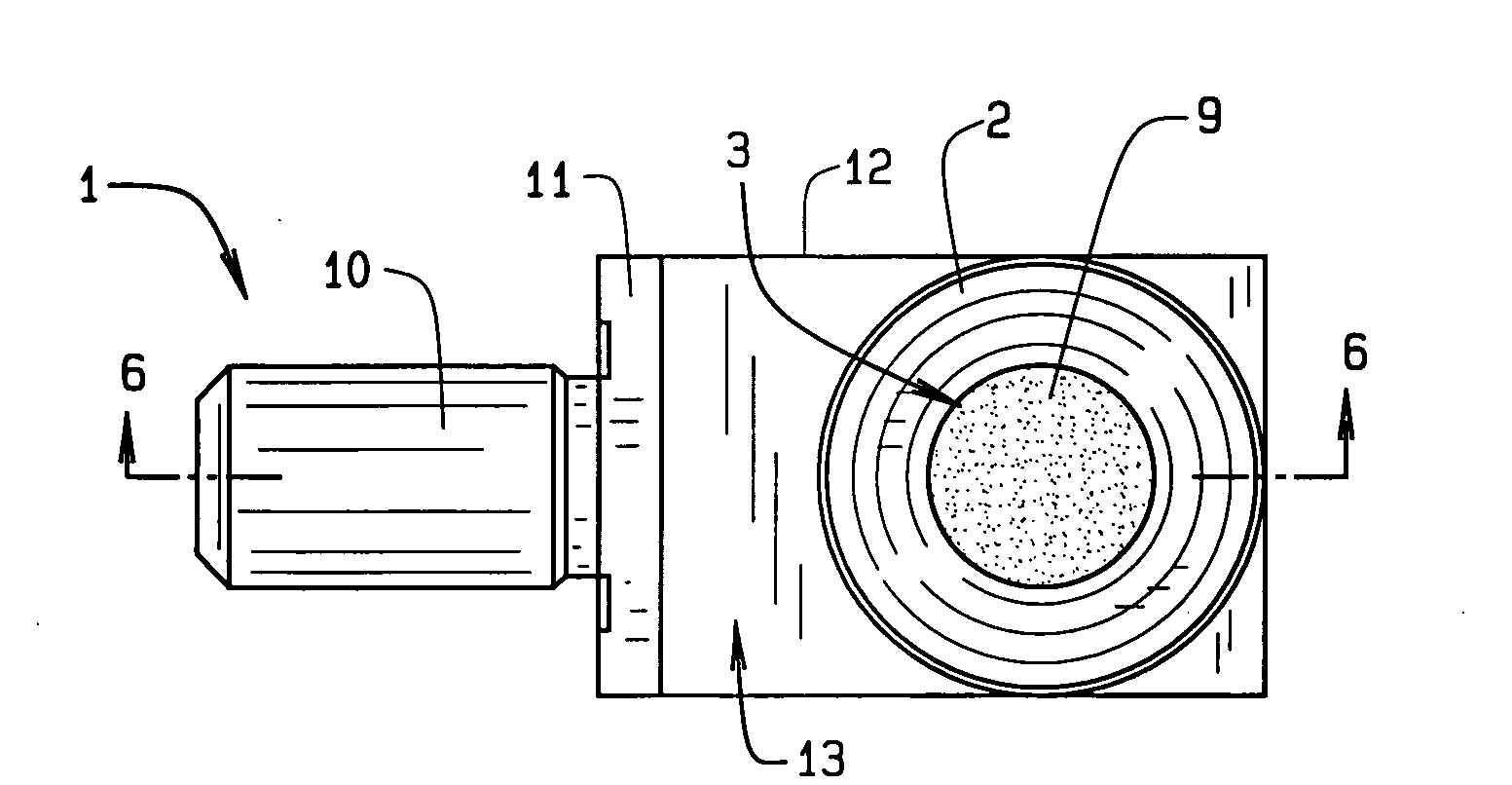
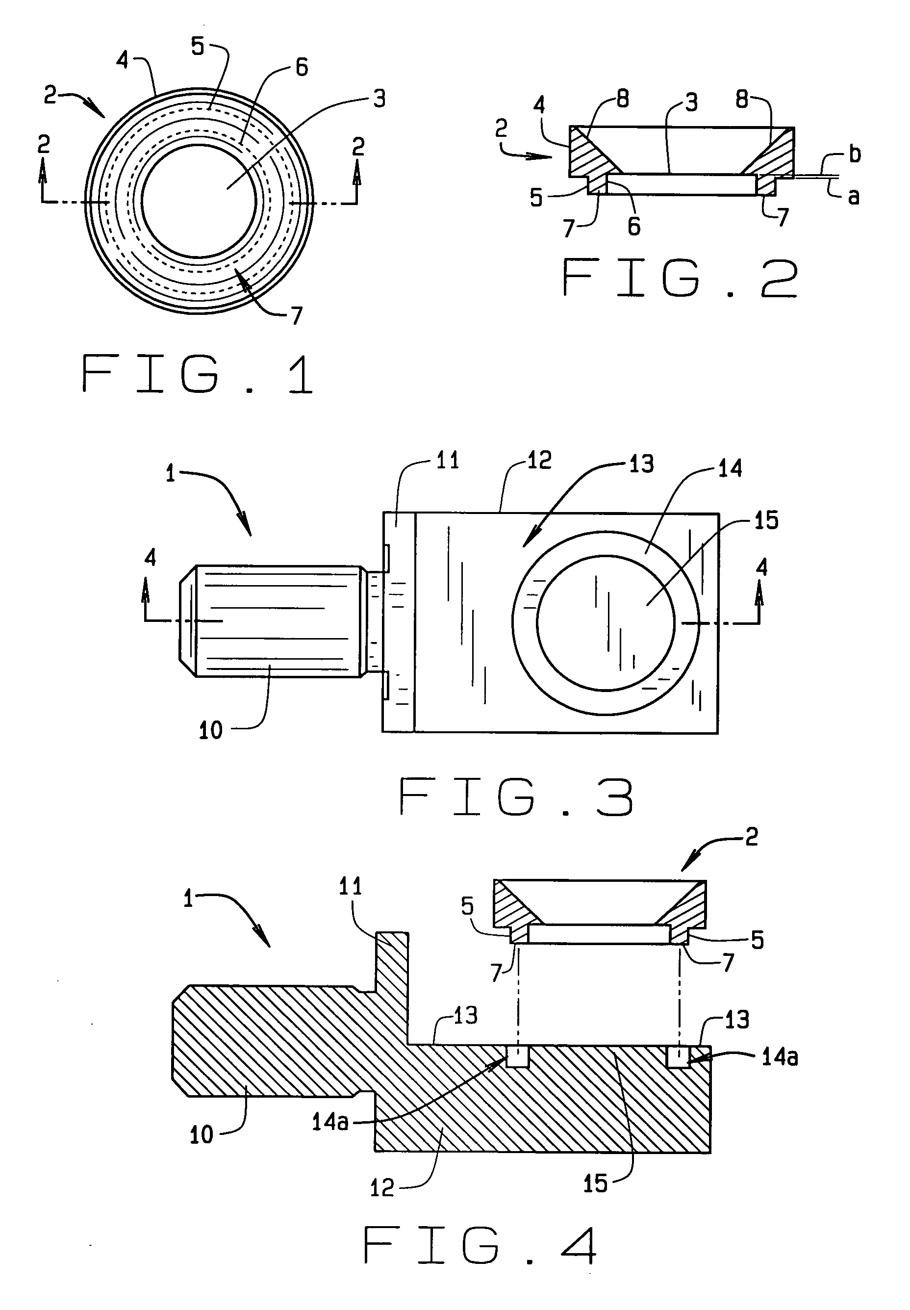
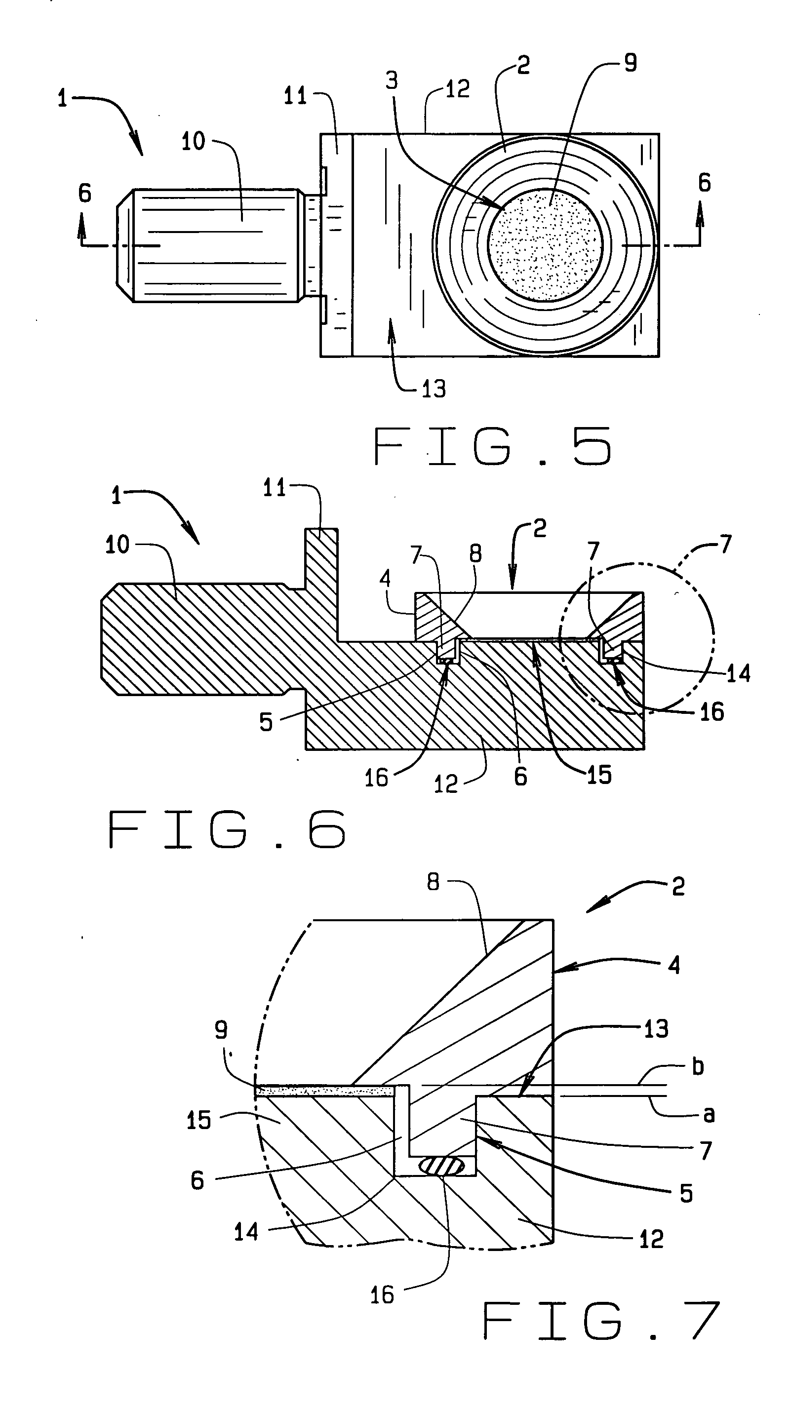
[0027]In referring to the drawings, FIG. 1 shows a ring 2 of the present invention, or target 1. The ring is generally round with a downwardly angled round inside face 8 that opens to a round aperture 3 of a known diameter. In this figure, the ring has an outer rim 4 which is generally the outside diameter of the ring, an inner rim 5 here shown in phantom and of lesser diameter than the outer rim, an inside rim 6 also in phantom and of lesser diameter than the inner rim, and an annulus 7 defined as the band located within the inner rim and the inside rim.

[0028]When viewed from the side in FIG. 2, the ring 2 has an upper thickness, a bottom below the surface 8, and with the annulus centered upon the bottom of the ring and outwardly of the aperture. The inside face 8 descends radially from the outer rim towards the aperture, generally at a forty five degree angle or bevel. Proximate the aperture, the inside face is offset 0.005 inch above the annulus where the offset is shown between ...


PUM


Abstract

A surveying type target has a precisely located aperture that achieves tolerances, within + / −0.0005 inch, in the assembly and usage of a retro-reflective photogrammetry target for use with close range industrial photogrammetry. The dot the target may also be refurbished and reconditioned in the field under all weather conditions. This target has a precisely machined ring that fits into a precisely machined socket of a body to eliminate assembly irregularities. This target precisely locates the ring upon the body forming a finished target with a known centerline and height location within + / −0.0005 inch tolerance.

Description

CROSS REFERENCE TO RELATED APPLICATION[0001]This provisional application claims priority to the non-provisional patent application Ser. No. 60 / 901,618, which was filed on Feb. 12, 2007, which claims to the non-provisional application for patent Ser. No. 11 / 325,972 which was filed on Jan. 4, 2006, which claims priority to the provisional application for patent Ser. No. 60 / 641,828 which was filed on Jan. 5, 2005 and all are commonly owned by the same inventor. This application is also related to U.S. Pat. No. 5,073,005 commonly owned by the same inventor.BACKGROUND OF THE INVENTION[0002]This invention relates generally to a target for retro-reflective photogrammetry that provides for critical detection of light from the strobe of a close range industrial photogrammetry camera, and more specifically to a precisely machined aperture ring and cooperating socket that defines a target assembly that provides for precise area and location of the target to within + / −0.0005 inch or less.[0003]...

Claims


Application Information

Patent Timeline
IPC IPC(8): G02B5/08
CPCG02B5/12
Inventor HUBBS, WILLIAM O.
Owner HUBBS MACHINE & MFG
Learn More